
Page 303 - Boiler_Operators_Handbook,_Second_Edition
P. 303
288 Boiler Operator’s Handbook
few rare Sterling designs, will be what we loosely term
“package types” that come in one of four basic arrange-
ments, A, D, O or Flexitube. These designs provide the
current optimum in cost and performance, some better
than others, and represent the heart of the packaged wa-
tertube boiler industry. A good understanding of their
construction and operation will serve you well in devel-
oping an understanding of any other watertube boiler
you come upon.
The A type (Figure 10-18) was originally developed
by the Saginaw Boiler Works in Michigan and subse-
quently purchased by Combustion Engineering. Other
manufacturers produce comparable designs. The A
shape is attributed to the single steam drum at the center
top and the two mud drums, commonly called head-
ers, at the bottom. They require a second blow down
line and more soot blowers but provided features like a
water cooled furnace from one end to the other and bal-
anced construction which makes them easy to transport
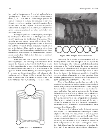
Figure 10-19. Tangent tube construction
as package boilers.
The tubes inside that form the furnace have al- Normally the bottom tubes are covered with re-
ternating shapes. One will drop from the steam drum fractory tile to limit heat absorption on the top of the
around the furnace and down into the bottom header tube. The tangent tube walls and installation of sealing
while the next tube turns above the bottom header and refractory in the “crotch” under the steam drum close
crosses the bottom of the furnace to enter the side of the the furnace so all the flame and flue gases are restricted
opposite bottom header. Shifting the tube arrangement to the center of the boiler. Four to eight rows of tubes
by one sets up the crossing pattern with a tangent tube from the back of the boiler are installed without the
wall construction (Figure 10-19) in most of the roof and drop to the bottom header forming tube gaps that allow
sides of the furnace. The furnace floor (the tubes at the the flue gases to turn and proceed down the convection
bottom) have a maximum spacing of one tube width. bank tubes back toward the front of the boiler.
Most of these boilers have the flue gas outlet at the
top front but some were made with the convection bank
terminated part way down the boiler to create a larger
furnace. In that case the side wall tubes are also the fur-
nace wall tubes. One serious problem with the A type
boiler is the crotch refractory falls out on occasion forc-
ing an outage of the boiler because a lot of capacity is
lost and there is concern for damage to the steam drum.
They’re also a pain to maintain because all the trim is
above the burner and fans and ductwork connected to
the burner at that point makes access to the front drum
manhole almost impossible.
The front wall of all these boiler designs is normal-
ly a simple 13-1/2 inch thickness consisting of 9 inches
of plastic refractory over 4-1/2 inches of insulating brick
with a 1/4- or 3/8-inch thick steel front wall plate. There
are variations in thickness and materials of construction
including use of ceramic wool, insulation instead of
brick and precast fired tile instead of the plastic refrac-
tory but all perform the basic function of closing the
Figure 10-18. “A” type boiler front wall. A few, very few, use additional tubes bent to