
Page 315 - Boiler_Operators_Handbook,_Second_Edition
P. 315
300 Boiler Operator’s Handbook
side so it illuminates the notches, they appear bright, cutoff is the primary protective device to save the boiler
almost white. Diffraction in the water shifts the light be- in the event the water level goes too low. The cutoff
low the water line so that portion of the glass containing must be installed in a manner that keeps it in position
water looks dark. relative to the boiler so thermal expansion doesn’t shift
When pressures get higher than 250 psig the glass it relative to the lowest safe water level. A low water
can’t withstand the heat of the steam so flat glass is used cutoff normally has a mark in the casting that indicates
with a thin sheet of mica (a mineral that forms natural its operating point. That level has to be higher than the
transparent sheets) installed between the gasket and lowest safe operating level established by the boiler
glass. manufacturer.
As pressures increase the problems with differ- If there’s no indication of that level in the docu-
ential expansion prevent use of full length glass so the mentation or on the boiler the bottom of the gauge glass
gauge glass is converted to several small round flat is a good place to set it. Since I’ve discovered cutoffs
glasses stacked one over the other on a steel frame. installed at different levels on identical boilers (they had
These have areas between each glass where the level replaced the piping but the contractor wasn’t concerned
isn’t visible. To allow differentiation of water and steam with matching construction) and cutoffs lowered by
the gauge glass is doubled up with another round flat maintenance personnel (the darn things kept shutting
glass behind installed at a slight angle to the other one. the boiler down) you should be aware that a low water
Lights shine through red and green lenses and through cutoff can be installed improperly. Any cutoff located
the gauge glass. Diffraction in this case determines significantly lower than the bottom of the gauge glass is
which color you see, red if the glass contains steam and a potential problem.
green if it’s under water. You should make it a point Any steam boiler should have two low water cut-
to carefully read and make sure you understand the offs (see why they fail at the end of the book) and they
manufacturer’s instructions for your gauge glass, it will should be piped to independent connections on the boil-
pay you by reducing the number of times you have to er. That way if one connection gets plugged the other
change it. cutoff can still work. Many are installed with a common
A problem with gauge glasses that I’ve seen recent- steam connection because they’re less likely to plug with
ly is regular packing leaks. Read the section on pumps two water leg connections (I have, however, seen a cou-
to get some guidance on how to install packing properly ple of steam lines to low water cutoffs plugged). If there
so you won’t have leaks right after you packed them. are valves located between the low water cutoffs and
Another technological advance is graphite tape which the boiler they should be full ported valves to reduce
can be wrapped around the glass to form a packing ring the potential for plugging and they must be rising stem
that will do an excellent job of sealing a gauge glass. type or quarter turn valves that indicate their position at
a glance.
Low Water Cutoff The drain valve for any low water cutoff should
Frequently integral with the water column, occa- always be a globe valve. Gate valves and quarter turn
sionally (on hot water boilers) built into the boiler, and valves do not throttle flow adequately to permit the op-
regularly mounted as an external device, a low water erator to drop the water level slowly.
The cutoff must be installed in such a manner that
it will drain back into the boiler. A major university lost
a brand new field erected boiler because the erector in-
stalled the cutoff in a trap (Figure 10-35). Notice that the
figure shows tees and crosses in the piping closed with
nipples and caps, that’s so you can gain access to the
piping to inspect it and, if necessary, clean it.
If your boiler has low water cutoffs at the front and
rear of the boiler don’t be surprised if they are not at the
same level. Since the fire is concentrated in the front of
the boiler a slope in the surface of the water in the boiler
from front to rear is not unusual. Depending on the dis-
tribution of the flue gas and tube arrangement the level
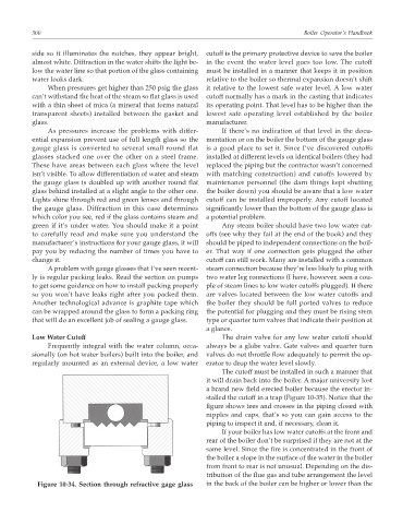
Figure 10-34. Section through refractive gage glass in the back of the boiler can be higher or lower than the