
Page 333 - Boiler_Operators_Handbook,_Second_Edition
P. 333
318 Boiler Operator’s Handbook
dumped enough oil in the furnace that the lighter por- about 5 to 1, some as high as 10 to 1.
tions, which evaporated, produced a flammable mixture The typical pressure atomizing burner is limited
that the ignitor managed to light! The resulting explo- in turndown capability to about 2 to 1. Once the flow
sion didn’t destroy the apartment building but it did is reduced to half (the pressure drop through the tip is
manage to destroy the boiler. one fourth) the velocities are so low that the oil doesn’t
Atomization is accomplished in different ways; break up well. Oil return atomizers were produced as
all of them work. The principle difference between a solution to that problem. The full load flow of oil is
them is the degree of turndown they can accomplish. delivered to the burner tip and flows through those slots
Pressure atomizing burners produce a fine spray pat- to produce the spinning that breaks up the oil. To reduce
tern of oil just like you do when you use a water hose the firing rate some of the oil is returned from the tip
to wash your car and pull the trigger on the sprayer to the suction of the fuel oil pumps. The turndown is
just enough to produce that fine conical mist of water. generally a function of the differential pressure where
The quality of the atomization varies with the pressure the turndown is equal to delivered oil pressure divided
drop across the burner tip. by one hundred. A system firing oil supplied at 300 psig
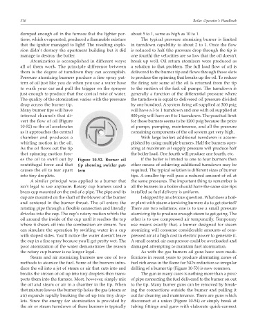
Many burner tips will have will have a 3 to 1 turndown and one with oil supplied at
internal channels that di- 800 psig will have an 8 to 1 turndown. The practical limit
vert the flow of oil (Figure for those burners seems to be 1200 psig because the price
10-52) so the oil accelerates of pumps, pumping, maintenance, and all the pressure
as it approaches the central containing components of the oil system get very high.
chamber and produces a With large boilers additional turndown is accom-
whirling motion in the oil. plished by using multiple burners. Half the burners oper-
As the oil flows out the tip ating at maximum oil supply pressure will produce half
that spinning motion forc- the boiler load. One fourth will produce one fourth, etc.
es the oil to swirl out by Figure 10-52. Burner oil If the boiler is limited to one to four burners then
centrifugal force and that tip showing swirler pat- other means of achieving additional turndown may be
causes the oil to tear apart tern required. The typical solution is different sizes of burner
into tiny droplets. tips. A smaller tip will pass a reduced amount of oil at
A similar principal was applied to a burner that the same pressures. The important thing to remember is
isn’t legal to use anymore. Rotary cup burners used a all the burners in a boiler should have the same size tips
brass cup mounted on the end of a pipe. The pipe and its installed so fuel delivery is uniform.
cup are mounted on the shaft of the blower of the burner I skipped by an obvious question. What does a boil-
and centered in the burner throat. The oil enters the er plant with steam atomizing burners do to get started?
rotating pipe through a flexible connection and literally There are two solutions, one is to use a small pressure
drizzles into the cup. The cup’s rotary motion whirls the atomizing tip to produce enough steam to get going. The
oil around the inside of the cup until it reaches the top other is to use compressed air temporarily. Temporary
where it shears off into the combustion air stream. You use means exactly that, a burner designed for steam
can simulate the operation by swirling water in a cup atomizing will consume considerable amounts of com-
with sloped sides. You’ll notice the water doesn’t leave pressed air at a high cost in electric power to generate it.
the cup in a fine spray because you’ll get pretty wet. The A small control air compressor could be overloaded and
poor atomization of the water demonstrates the reason damaged attempting to maintain fuel atomization.
the rotary cup burner is no longer legal. As with the gas burners oil guns have seen modi-
Steam and air atomizing burners use one of two fications in recent years to produce alternating zones of
methods to atomize the fuel. Some of the burners intro- fuel rich areas in the flame for NOx reduction so irregular
duce the oil into a jet of steam or air that cuts into and drilling of a burner tip (Figure 10-53) is now common.
breaks the stream of oil up into tiny droplets then trans- The gun in many cases is nothing more than a piece
ports them into the furnace. Most, however, simply mix of pipe connecting the fuel delivered to the burner on out
the oil and steam or air in a chamber in the tip. When to the tip. Many burner guns can be removed by break-
that mixture leaves the burner tip holes the gas (steam or ing the connections outside the burner and pulling it
air) expands rapidly breaking the oil up into tiny drop- out for cleaning and maintenance. There are guns which
lets. Since the energy for atomization is provided by disconnect at a union (Figure 10-54) or simply break at
the air or steam turndown of these burners is typically tubing fittings and guns with elaborate quick-connect