
Page 336 - Boiler_Operators_Handbook,_Second_Edition
P. 336
Plants and Equipment 321
tion of the oil stream as it leaves the tip. Operators that As the coal is pushed up it is mixed with air enter-
get frustrated with the brass tools and wire brushes then ing via the tuyeres (C in Figure 10-59), pipes, tubes or
resort to steel tools and wire brushes to round off those slots in the grate that admit the air into the furnace. The
sharp edges so the oil stream doesn’t make a sharp break mixture is ignited by coal already burning above the
with the tip; some of the oil tends to follow the curved grate. The coal air mixture partially burns on the grate
edges created by abrading the tip with steel tools and and completes burning of hydrocarbons vaporized by
that oil forms carbon very quickly. Save yourself a lot of the heat of the furnace in the space immediately above
trouble and stick with the brass tools. the grate. Air at the tuyeres and most active portion of
the grate is considered primary air and is controlled by
Coal Stokers dampers supplying the air to the primary air zone (B).
Don’t skip this part too quickly. We have a very As the hydrocarbons and sulfur in the coal are
limited supply of natural gas and oil in the world but, consumed the remaining ash is pushed to the edge or
at our present rate of consumption, over one thousand sides of the grate where it can be removed by hand or
years of coal. Despite the many undesirable features of dumped (D) for removal by hand or screw conveyor.
coal firing it’s the one fuel that will always be available For final burnout and handling high loads temporarily a
in the future. controlled flow of air is supplied to the dump grate zone
There are many options for introducing coal into a at (E) which must be reduced dramatically to permit
furnace and “coal burner” and “stoker”
provide some differentiation. Stokers
handle coal as a solid material. Coal
firing can be as simple as a grate in the
bottom of a furnace with openings for
the air and an individual opening a door
in the side of the boiler to introduce the
coal with a shovel. It can be as com-
plex as a multi-tiered tangentially fired
furnace with over-fire air ports and re-
burners.
I’ve seen a few of the first type in
small plants throughout the country
and only photographs and drawings
of the latter. I don’t expect many of the
operators reading this book to be work-
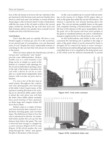
ing in an electrical utility plant which Figure 10-57. Coal screw conveyor
is about the only place you will find
the latter. Since utility plants normally
have good training of their operators
on those large and complex boilers I’ll
leave that to them.
Stokers come in a variety of forms
and have basically been reduced to un-
der-feed, traveling grate, and over-feed
types. The difference in these is how the
coal is introduced to the fire. An under-
feed stoker pushes the coal up into the
furnace from below the grate. The coal
is removed from storage or a hopper by
a screw conveyor (Figure 10-57) or ram
(Figure 10-58) which pushes the coal
along through the “retort” and against
the pile in the bottom of the furnace. Figure 10-58. Underfeed stoker ram