
Page 334 - Boiler_Operators_Handbook,_Second_Edition
P. 334
Plants and Equipment 319
capabilities, with many variations in between. Most ar- Sometimes it’s using a softer material like brass, nor-
rangements are specific to a particular manufacturer but mally on the gun, that will deform under the pressure
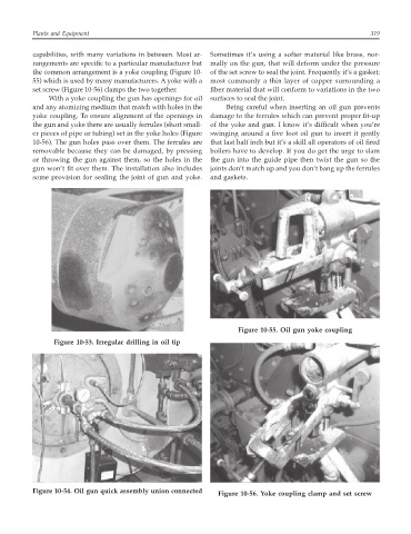
the common arrangement is a yoke coupling (Figure 10- of the set screw to seal the joint. Frequently it’s a gasket;
55) which is used by many manufacturers. A yoke with a most commonly a thin layer of copper surrounding a
set screw (Figure 10-56) clamps the two together. fiber material that will conform to variations in the two
With a yoke coupling the gun has openings for oil surfaces to seal the joint.
and any atomizing medium that match with holes in the Being careful when inserting an oil gun prevents
yoke coupling. To ensure alignment of the openings in damage to the ferrules which can prevent proper fit-up
the gun and yoke there are usually ferrules (short small- of the yoke and gun. I know it’s difficult when you’re
er pieces of pipe or tubing) set in the yoke holes (Figure swinging around a five foot oil gun to insert it gently
10-56). The gun holes pass over them. The ferrules are that last half inch but it’s a skill all operators of oil fired
removable because they can be damaged, by pressing boilers have to develop. If you do get the urge to slam
or throwing the gun against them, so the holes in the the gun into the guide pipe then twist the gun so the
gun won’t fit over them. The installation also includes joints don’t match up and you don’t bang up the ferrules
some provision for sealing the joint of gun and yoke. and gaskets.
Figure 10-55. Oil gun yoke coupling
Figure 10-53. Irregular drilling in oil tip
Figure 10-54. Oil gun quick assembly union connected Figure 10-56. Yoke coupling clamp and set screw