
Page 351 - Boiler_Operators_Handbook,_Second_Edition
P. 351
336 Boiler Operator’s Handbook
help to realize that a centrifugal pump simply boosts the
pressure a certain amount and that boost is related to the
flow of water through the pump. You can stop stirring
the water in your bowl and it will still overflow once it
has filled. You can also vary the difference (head) you’re
creating by changing the speed at which you stir it.
Back from playing in the kitchen sink? Good. I
trust you now understand that there is no such thing as
a limit on the flow through a centrifugal pump; the high-
est possible flow is much more than the design value
and the minimum is zero. Without check valves in the
discharge piping a higher external differential pressure
than the pump can handle will result in flow backwards
through the pump. The actual flow rate is dependent on
the performance of the pump itself and the difference in
pressure between suction and discharge.
Oh there’s a design point, a flow and differential
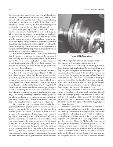
that the engineer calculated for selecting the pump and Figure 10-72. Wear rings
that’s usually indicated in the manual and on the pump
curve. What you, as an operator, have to deal with is the ring and casing where erosion can cause problems. Too
actual flowing conditions. The odds that the actual con- thin a gasket will normally bind the pump up.
ditions are precisely the same as the design conditions You’ll find a lot of variety in centrifugal pumps
are between slim and none. depending on their application. The pressure differential
A feature of centrifugal pumps that’s frequently they can produce depends on the density of the liquid be-
forgotten is the use of wear rings (Figure 10-72) The ing pumped and the speed of the tips of the vanes in the
space between the casing and the eye of the impeller impeller. To make a pump operate at a higher differential
is all that separates the suction and discharge pressure pressure with the same liquid the diameter of the impel-
zones of the pump so some water has to bleed back ler is increased. Once the impeller’s maximum diameter
through that space because they can’t rub. As the pump is reached a faster motor is used. As the impeller diameter
is used small particles in the liquid and the liquid itself and speed increases the stress on the metal gets higher so
can erode the material on either side of that gap and pro- there are practical limits on the pressure boost.
vision of wear rings makes it possible to restore a pump If a larger differential pressure is required the
to a like-new condition by simply replacing the wear pump is supplied with additional impellers. We call
rings. The casing wear rings, right one hanging loose in them ‘multi-stage’ pumps. The pressure is increased a
the photo, are keyed to set in the casing and not rotate. little in each impeller which, along with its volute and
The impeller wear ring is heated then inserted onto the share of the casing constitutes a stage. That way high
end of the impeller where it shrinks on for a tight fit. pressures can be developed without making pumps of
No, a strainer in the suction piping (standard re- very large diameter.
quirement for most pumps) does not remove the small Since the eye (inlet of an impeller) is exposed to
particles that erode the wear rings; the strainer does suction pressure at that stage and the rest is exposed to
remove pieces that would jam between them. Usually the discharge pressure of that stage there’s a difference
a pump with wear rings will also have a shaft sleeve. I in axial forces on the stage (Figure 10-73). In single stage
should mention that you should be cautious when re- pumps holes are drilled through the back plate of the
placing wear rings and anytime you reassemble a split impeller and a second set of wear rings added to bal-
case pump because the outer wear ring can be distorted ance the pressure. (Figure 10-74) In multi-stage pumps
when the two halves of the pump casing bear down the stages are reversed on the shaft (Figure 10-75) so the
on it. Always make sure the pump rotates by hand as imbalance of one stage is opposed by the imbalance of
you’re drawing up on the bolts that hold the two casing another. Some pumps with vertical shafts are designed
halves together. Also, don’t install a thicker gasket on a so the axial thrust helps offset the weight of the shaft
pump simply because you don’t have the right thickness and impeller. Despite the best design, there’s no guaran-
on hand, that will create gaps between the outer wear tee the pump will not see some axial forces so one end