
Page 356 - Boiler_Operators_Handbook,_Second_Edition
P. 356
Plants and Equipment 341
I don’t care for centrifugal feed pumps in heating occurrence with a heavy load, the turbine pump output
plants because they can’t handle the pressure variations. will only increase a little bit but the centrifugal pump
Take the typical heating boiler plant. Both centrifugal will increase its delivery over twice as much. That ad-
and turbine pumps can be obtained to produce a design ditional water consumes more of the boiler’s heat input
flow of about 31 gpm (15,500 pph) at the normal boiler leaving less to make steam so the pressure drops further.
operating pressure of 12 psig (31.7 feet). The density of I think this shows that a poor choice in boiler feed pump
water for this example is assumed to be 54.55 pounds selection on low pressure boilers can produce serious
per cubic feet, 175°F water, which means the head rela- headaches for the boiler operator. Replacing those cen-
tionship is 2.64 feet per psi. There is a big difference in trifugals with turbine pumps can reduce the swinging
their operation as the pressure changes. They’re selected pressure problems encountered in some plants and
for when the boiler runs up to the limit of the safety eliminate others because the pumps create the problem.
valves (15 psig or 39.5 feet).
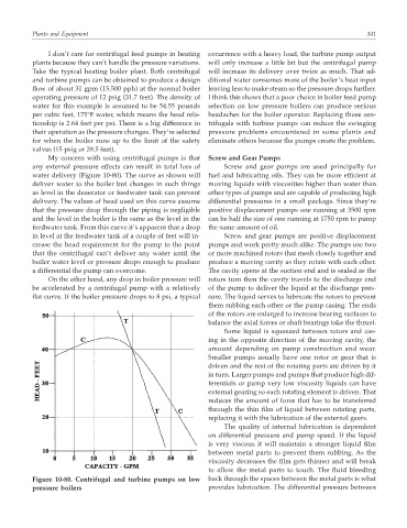
My concern with using centrifugal pumps is that Screw and Gear Pumps
any external pressure effects can result in total loss of Screw and gear pumps are used principally for
water delivery (Figure 10-80). The curve as shown will fuel and lubricating oils. They can be more efficient at
deliver water to the boiler but changes in such things moving liquids with viscosities higher than water than
as level in the deaerator or feedwater tank can prevent other types of pumps and are capable of producing high
delivery. The values of head used on this curve assume differential pressures in a small package. Since they’re
that the pressure drop through the piping is negligible positive displacement pumps one running at 3500 rpm
and the level in the boiler is the same as the level in the can be half the size of one running at 1750 rpm to pump
feedwater tank. From this curve it’s apparent that a drop the same amount of oil.
in level at the feedwater tank of a couple of feet will in- Screw and gear pumps are positive displacement
crease the head requirement for the pump to the point pumps and work pretty much alike. The pumps use two
that the centrifugal can’t deliver any water until the or more machined rotors that mesh closely together and
boiler water level or pressure drops enough to produce produce a moving cavity as they rotate with each other.
a differential the pump can overcome. The cavity opens at the suction end and is sealed as the
On the other hand, any drop in boiler pressure will rotors turn then the cavity travels to the discharge end
be accelerated by a centrifugal pump with a relatively of the pump to deliver the liquid at the discharge pres-
flat curve. If the boiler pressure drops to 8 psi, a typical sure. The liquid serves to lubricate the rotors to prevent
them rubbing each other or the pump casing. The ends
of the rotors are enlarged to increase bearing surfaces to
balance the axial forces or shaft bearings take the thrust.
Some liquid is squeezed between rotors and cas-
ing in the opposite direction of the moving cavity, the
amount depending on pump construction and wear.
Smaller pumps usually have one rotor or gear that is
driven and the rest of the rotating parts are driven by it
in turn. Larger pumps and pumps that produce high dif-
ferentials or pump very low viscosity liquids can have
external gearing so each rotating element is driven. That
reduces the amount of force that has to be transferred
through the thin film of liquid between rotating parts,
replacing it with the lubrication of the external gears.
The quality of internal lubrication is dependent
on differential pressure and pump speed. If the liquid
is very viscous it will maintain a stronger liquid film
between metal parts to prevent them rubbing. As the
viscosity decreases the film gets thinner and will break
to allow the metal parts to touch. The fluid bleeding
Figure 10-80. Centrifugal and turbine pumps on low back through the spaces between the metal parts is what
pressure boilers provides lubrication. The differential pressure between