
Page 357 - Boiler_Operators_Handbook,_Second_Edition
P. 357
342 Boiler Operator’s Handbook
each adjoining cavity pushes the fluid through so it
wedges its way between the part. If pressure differen-
tials are considerably lower than design there may not
be sufficient differential to force the lubrication of the
pump. If the pump speed is too low it won’t generate
that wedge effect as well so other factors like the viscos-
ity of the liquid have to aid in lubrication.
The typical pump used for pumping heavy fuel oil
will not effectively pump light fuel oil and may even fail
if used to pump light fuel oil. Some people argue that
a heavy oil pump is worn by the ash and sediment in Figure 10-81. Gear pump
the oil so the gaps between rotors and casing have in-
creased. However, the truth of the matter is the pump’s
design and speed were established for heavy oil and
don’t work well on light oil. The lower the viscosity the
faster the pump has to run.
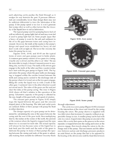
Figures 10-81, 10-82, and 10-83 are the typical
forms of screw and gear pumps used in boiler plants.
A common gear pump consists of two gears in a casing.
Usually one is driven and the other is an ‘idler.’ We use
the term idler to imply it doesn’t transmit power to any-
thing else, not that it’s lazy. The teeth of the driven gear
engage in the teeth of the idler and they counter-rotate.
Let’s start with the gear pump in Figure 10-81. The liq- Figure 10-82. Crescent gear pump
uid enters the pump where the gear teeth are disengag-
ing, is trapped within the cavities formed between the
teeth and casing and is carried to the discharge side of
the pump where it is forced out as the two gears engage,
filling the cavity the liquid was in with a tooth of the
other gear. A sectional view in the other direction would
not reveal much. The sides of the gears are flat and just
clear flat sides of the pump casing. The view in Figure
10-81 shows all that’s relative to the operation of the
pump. Volumetric capacity of the pump is affected by
the size, length of the gear teeth, and speed of rotation.
The crescent gear pump in Figure 10-82 simply
Figure 10-83. Screw pump
traps the liquid between the gears and the crescent
shaped piece of the housing. The inlet and outlet ports through adjustment.
are outlined. Either of these pumps will pump the fluid The cavity in a screw pump (Figure 10-83) is formed
in either direction. by the intersection of the rotors and closed by the casing
The design capacity of a gear pump can be deter- housing the rotors. The pump shown is supplied with
mined by calculating the area of the space between the two idler rotors that increases it’s capacity without an ap-
casing and the root of the gear teeth, then multiplying preciable change in size. A smaller pump can be had with
that by the radius at the center of the teeth, the percent only two rotors. Liquid enters the pump at one end of the
of the rotation where the liquid is trapped and the rpm rotors, fills a cavity that opens as the grooves in the rotors
times two to account for each side. The actual capacity separate, is trapped between the casing and rotors as the
will always be less because some of the liquid has to grooves engage, then travels along the rotors to the dis-
leak back past the teeth and the ends of the gears to charge end of the pump. That movement and the differ-
lubricate the pump. In many of these pumps the spac- ence between suction and discharge pressures produces
ing between the casing and ends of the gears is adjust- an axial thrust on the pump that has to be opposed by
able making them suitable for different viscosity fluids the bearing of the driven rotor and the fluid film between