
Page 362 - Boiler_Operators_Handbook,_Second_Edition
P. 362
Plants and Equipment 347
Figure 10-86. Centrifugal fan shape
as opposed to blower
can break and the rest can still carry normal loads. The
problem is that the one belt that breaks usually gets
tangled with the others with complete failure. I don’t
like belt driven fans and blowers and believe that there
are a sufficient number of choices of fans at standard
motor speeds to use direct drive fans on boilers. With
the growth of variable speed drives where we can run a
fan at any speed we choose we don’t need belts. I’m defi-
nitely opposed to belts because they’re a maintenance
item and produce unnecessary radial loads on fan shafts
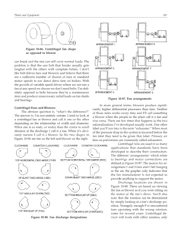
Figure 10-87. Fan arrangements
and bearings.
In more general terms, blowers produce signifi-
Centrifugal Fans and Blowers
cantly higher differential pressures than fans. Neither
The obvious question is, “what’s the difference?”
of those rules works every time and I’ll call something
The answer is, I’m not entirely certain. I tend to look at
a blower when the people in the plant call it a fan and
a centrifugal fan or blower and call it one or the other
vice versa. There are few times that happens so the two
depending on the relationship of width and diameter.
rationalizations I’ve developed usually work. One other
When one is as wide, or wider, than the center to scroll
label you’ll run into is the term “exhauster.” When most
distance at the discharge I call it a fan. When it’s obvi-
of the pressure drop in the system is incurred before the
ously narrow I call it a blower. So the two shapes in
fan inlet they tend to be given that label. Primary air
Figure 10-86 are fan on the left and blower on the right.
fans on pulverizers are commonly called exhausters.
Centrifugal fans are used in so many
applications that standards have been
developed to describe their construction.
The different ‘arrangements’ which relate
to bearings and motor connections are
defined in Figure 10-87. The motors for ar-
rangement 1 and 3 fans aren’t left hanging
in the air, the graphic only indicates that
the fan manufacturer is not expected to
provide anything to support the motor.
Discharge locations are shown in
Figure 10-88. These are based on viewing
the fan or blower as if you were sitting on
the motor or the fan’s sheve. You’ll also
note that the rotation can be determined
by simply looking at a fan’s discharge po-
sition. Strangely enough I’ve encountered
fans operating with the wrong rotation,
some for several years. Centrifugal de-
Figure 10-88. Fan discharge designations vices will work with either rotation, only