
Page 365 - Boiler_Operators_Handbook,_Second_Edition
P. 365
350 Boiler Operator’s Handbook
curves relate to the damper’s wide open pressure drop
divided by the maximum system differential pressure.
In the most common fan application that requires
air flow control, forced draft fans, variable inlet vanes
are typically used to reduce fan horsepower require-
ments. Variable inlet vanes (VIVs, Figure 10-92) on the
inlet of a forced draft fan not only act as dampers but
also put a swirl on the air as it enters the fan. By turning
the vanes in a way that puts a twist on the air entering
the fan the air is rotated in the direction of fan wheel
rotation. The inlet vanes reduce fan motor horsepower
because they swirl the air so the fan doesn’t have to.
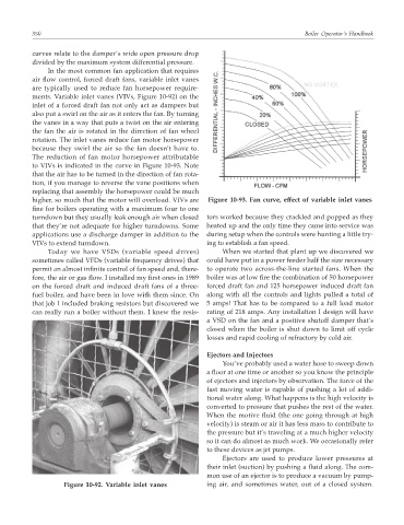
The reduction of fan motor horsepower attributable
to VIVs is indicated in the curve in Figure 10-93. Note
that the air has to be turned in the direction of fan rota-
tion, if you manage to reverse the vane positions when
replacing that assembly the horsepower could be much
higher, so much that the motor will overload. VIVs are Figure 10-93. Fan curve, effect of variable inlet vanes
fine for boilers operating with a maximum four to one
turndown but they usually leak enough air when closed tors worked because they crackled and popped as they
that they’re not adequate for higher turndowns. Some heated up and the only time they came into service was
applications use a discharge damper in addition to the during setup when the controls were hunting a little try-
VIVs to extend turndown. ing to establish a fan speed.
Today we have VSDs (variable speed drives) When we started that plant up we discovered we
sometimes called VFDs (variable frequency drives) that could have put in a power feeder half the size necessary
permit an almost infinite control of fan speed and, there- to operate two across-the-line started fans. When the
fore, the air or gas flow. I installed my first ones in 1989 boiler was at low fire the combination of 50 horsepower
on the forced draft and induced draft fans of a three- forced draft fan and 125 horsepower induced draft fan
fuel boiler, and have been in love with them since. On along with all the controls and lights pulled a total of
that job I included braking resistors but discovered we 5 amps! That has to be compared to a full load motor
can really run a boiler without them. I knew the resis- rating of 218 amps. Any installation I design will have
a VSD on the fan and a positive shutoff damper that’s
closed when the boiler is shut down to limit off cycle
losses and rapid cooling of refractory by cold air.
Ejectors and Injectors
You’ve probably used a water hose to sweep down
a floor at one time or another so you know the principle
of ejectors and injectors by observation. The force of the
fast moving water is capable of pushing a lot of addi-
tional water along. What happens is the high velocity is
converted to pressure that pushes the rest of the water.
When the motive fluid (the one going through at high
velocity) is steam or air it has less mass to contribute to
the pressure but it’s traveling at a much higher velocity
so it can do almost as much work. We occasionally refer
to these devices as jet pumps.
Ejectors are used to produce lower pressures at
their inlet (suction) by pushing a fluid along. The com-
mon use of an ejector is to produce a vacuum by pump-
Figure 10-92. Variable inlet vanes ing air, and sometimes water, out of a closed system.