
Page 353 - Boiler_Operators_Handbook,_Second_Edition
P. 353
338 Boiler Operator’s Handbook
when surging and that’s another thing to look for when increases the pressure drop in the system also rides up
monitoring the operation of a centrifugal pump. the pump curve to increase the pump differential by the
Someone is bound to say they have a pump with same amount.
that curve shape and don’t have a problem with it. I The rule of these curves is that the operating point
know there’s many a situation where the hump in the is where the system curve and the pump curve intersect.
curve is no problem. That’s because the change in flow It’s the only point where both the pump and system
normally produces a change in pressure drop through have the same characteristics. If, however, one or the
the system. You’ll remember in the chapter on flow other didn’t change then the flow through the system
where we found the change in pressure drop is pro- would be constant and we couldn’t control the water
portional to the square of the change in flow. With that flow. A control valve somewhere in the system or the
knowledge and some actual operating conditions you differential at zero flow (the point where the system
can spot the system flow curve on a pump curve to see curves intersect the zero flow line) has to change to vary
when the problem of surging will occur. the flow. Picture the system curves being shifted up and
First you look at the difference in pressure when down by the operation of the flow control valve and
there’s nothing flowing, a piece of data that’s not always you’ll notice how a curve like the one labeled B can hit
easy to measure. Then note differences in pressure in the two points on the pump curve.
system to find the loss due to flow at some point. Draw If you have a problem with a surging pump this
a system curve on the pump curve by starting with the should be a clue to you on how to handle it; simply
difference in pressure when nothing’s flowing then add increase system resistance when operating at the lower
the pressure drop for corresponding flows to continue it. loads by throttling a valve someplace. Alternative-
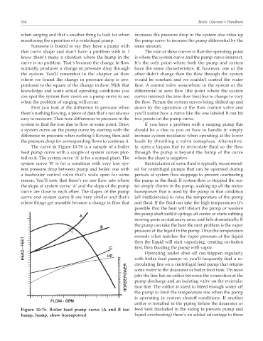
The curve in Figure 10-76 is a sample of a boiler ly, open a bypass line to recirculate fluid so the flow
feed pump curve with a couple of system curves plot- through the pump is beyond the hump of the curve
ted on it. The system curve ‘A’ is for a normal plant. The where the slope is negative.
system curve ‘B’ is for a condition with very low sys- Recirculation of some fluid is typically recommend-
tem pressure drop between pump and boiler, one with ed for centrifugal pumps that can be operated during
a feedwater control valve that’s wide open for some periods of system flow stoppage to prevent overheating
reason. You’ll note that there’s no one flow rate where the pump or the fluid. If system flow is stopped the wa-
the slope of system curve ‘A’ and the slope of the pump ter simply churns in the pump, soaking up all the motor
curve are close to each other. The slopes of the pump horsepower that is used by the pump in that condition
curve and system curve B are very similar and that’s (all inefficiencies) to raise the temperature of the pump
where things get unstable because a change in flow that and fluid. If the fluid can take the high temperatures it’s
possible that the heat will distort the pump or weaken
the pump shaft until it springs off center or starts rubbing
moving parts on stationary ones, and fails dramatically. If
the pump can take the heat the next problem is the vapor
pressure of the liquid in the pump. Once the temperature
exceeds what matches the vapor pressure of the liquid
then the liquid will start vaporizing, creating cavitation
first, then flooding the pump with vapor.
Operating under shut-off can happen regularly
with boiler feed pumps so you’ll frequently find a re-
circulating line on a centrifugal feed pump that returns
some water to the deaerator or boiler feed tank. On most
jobs the line has an orifice between the connection at the
pump discharge and an isolating valve on the recircula-
tion line. The orifice is sized to bleed enough water off
the pump to limit the temperature rise when the pump
is operating in system shutoff conditions. If another
orifice is installed in the piping before the deaerator or
Figure 10-76. Boiler feed pump curve (A and B (no feed tank (included in the sizing to prevent pump and
hump, hump, show horsepower) liquid overheating) there’s an added advantage to these