
Page 110 - Boiler plant and distribution system optimization manual
P. 110
Boiler Tuneup 95
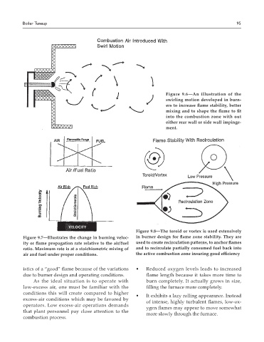
Figure 9.6—An illustration of the
swirling motion developed in burn-
ers to increase flame stability, better
mixing and to shape the flame to fit
into the combustion zone with out
either rear wall or side wall impinge-
ment.
velocity
Figure 9.8—The toroid or vortex is used extensively
Figure 9.7—Illustrates the change in burning veloc- in burner design for flame zone stability. They are
ity or flame propagation rate relative to the air/fuel used to create recirculation patterns, to anchor flames
ratio. Maximum rate is at a stoichiometric mixing of and to recirculate partially consumed fuel back into
air and fuel under proper conditions. the active combustion zone insuring good efficiency
istics of a “good” flame because of the variations • Reduced oxygen levels leads to increased
due to burner design and operating conditions. flame length because it takes more time to
As the ideal situation is to operate with burn completely. It actually grows in size,
low-excess air, one must be familiar with the filling the furnace more completely.
conditions this will create compared to higher
• It exhibits a lazy rolling appearance. Instead
excess-air conditions which may be favored by
of intense, highly turbulent flames, low-ox-
operators. Low excess-air operations demands
ygen flames may appear to move somewhat
that plant personnel pay close attention to the
more slowly through the furnace.
combustion process.