
Page 93 - Boiler plant and distribution system optimization manual
P. 93
78 Boiler Plant and Distribution System Optimization Manual
JACKSHAFT CONTROL SYSTEMS tioning control provides a margin of safety that is
not available in parallel positioning control.
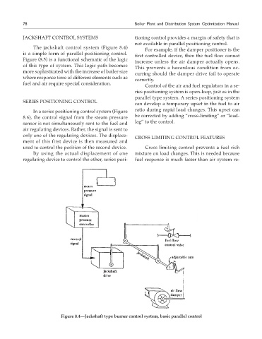
The jackshaft control system (Figure 8.4)
For example, if the damper positioner is the
is a simple form of parallel positioning control.
first controlled device, then the fuel flow cannot
Figure (8.5) is a functional schematic of the logic
increase unless the air damper actually opens.
of this type of system. This logic path becomes
This prevents a hazardous condition from oc-
more sophisticated with the increase of boiler size
curring should the damper drive fail to operate
where response time of different elements such as
correctly.
fuel and air require special consideration.
Control of the air and fuel regulators in a se-
ries positioning system is open-loop, just as in the
parallel type system. A series positioning system
SERIES POSITIONING CONTROL
can develop a temporary upset in the fuel to air
In a series positioning control system (Figure ratio during rapid load changes. This upset can
8.6), the control signal from the steam pressure be corrected by adding “cross-limiting” or “lead-
sensor is not simultaneously sent to the fuel and lag” to the control.
air regulating devices. Rather, the signal is sent to
only one of the regulating devices. The displace-
CROSS LIMITING CONTROL FEATURES
ment of this first device is then measured and
used to control the position of the second device. Cross limiting control prevents a fuel rich
By using the actual displacement of one mixture on load changes. This is needed because
regulating device to control the other, series posi- fuel response is much faster than air system re-
Figure 8.4—Jackshaft type burner control system, basic parallel control