
Page 193 - Bridge and Highway Structure Rehabilitation and Repair
P. 193
168 SECTION 2 STRENGTHENING AND REPAIR WORK
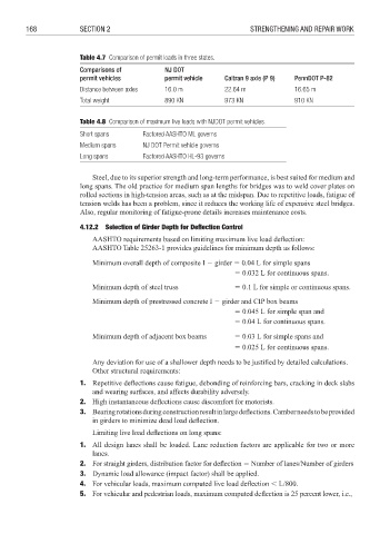
Table 4.7 Comparison of permit loads in three states.
Comparisons of NJ DOT
permit vehicles permit vehicle Caltran 9 axle (P 9) PennDOT P-82
Distance between axles 16.0 m 22.64 m 16.65 m
Total weight 890 KN 973 KN 910 KN
Table 4.8 Comparison of maximum live loads with NJDOT permit vehicles.
Short spans Factored AASHTO ML governs
Medium spans NJ DOT Permit vehicle governs
Long spans Factored AASHTO HL-93 governs
Steel, due to its superior strength and long-term performance, is best suited for medium and
long spans. The old practice for medium span lengths for bridges was to weld cover plates on
rolled sections in high-tension areas, such as at the midspan. Due to repetitive loads, fatigue of
tension welds has been a problem, since it reduces the working life of expensive steel bridges.
Also, regular monitoring of fatigue-prone details increases maintenance costs.
4.12.2 Selection of Girder Depth for Defl ection Control
AASHTO requirements based on limiting maximum live load defl ection:
AASHTO Table 25263-1 provides guidelines for minimum depth as follows:
Minimum overall depth of composite I 6 girder 3 0.04 L for simple spans
3 0.032 L for continuous spans.
Minimum depth of steel truss 3 0.1 L for simple or continuous spans.
Minimum depth of prestressed concrete I 6 girder and CIP box beams
3 0.045 L for simple span and
3 0.04 L for continuous spans.
Minimum depth of adjacent box beams 3 0.03 L for simple spans and
3 0.025 L for continuous spans.
Any deviation for use of a shallower depth needs to be justified by detailed calculations.
Other structural requirements:
1. Repetitive deflections cause fatigue, debonding of reinforcing bars, cracking in deck slabs
and wearing surfaces, and affects durability adversely.
2. High instantaneous deflections cause discomfort for motorists.
3. Bearing rotations during construction result in large deflections. Camber needs to be provided
in girders to minimize dead load defl ection.
Limiting live load deflections on long spans:
1. All design lanes shall be loaded. Lane reduction factors are applicable for two or more
lanes.
2. For straight girders, distribution factor for defl ection 3 Number of lanes/Number of girders
3. Dynamic load allowance (impact factor) shall be applied.
4. For vehicular loads, maximum computed live load defl ection : L/800.
5. For vehicular and pedestrian loads, maximum computed deflection is 25 percent lower, i.e.,