
Page 151 - Build Your Own Quadcopter_ Power Up Your Designs with the Parallax Elev-8
P. 151
130 Bu il d Y o ur O w n Q u a d c o p t e r
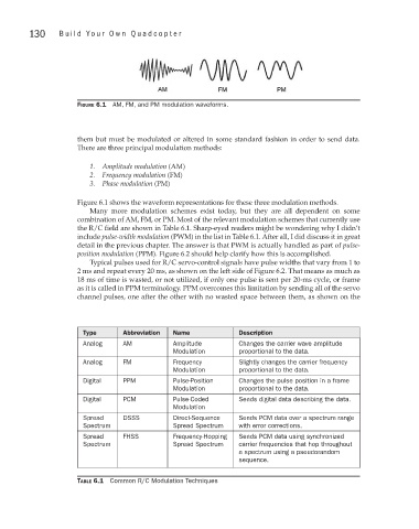
Figure 6.1 AM, FM, and PM modulation waveforms.
them but must be modulated or altered in some standard fashion in order to send data.
There are three principal modulation methods:
1. Amplitude modulation (AM)
2. Frequency modulation (FM)
3. Phase modulation (PM)
Figure 6.1 shows the waveform representations for these three modulation methods.
Many more modulation schemes exist today, but they are all dependent on some
combination of AM, FM, or PM. Most of the relevant modulation schemes that currently use
the R/C field are shown in Table 6.1. Sharp-eyed readers might be wondering why I didn’t
include pulse-width modulation (PWM) in the list in Table 6.1. After all, I did discuss it in great
detail in the previous chapter. The answer is that PWM is actually handled as part of pulse-
position modulation (PPM). Figure 6.2 should help clarify how this is accomplished.
Typical pulses used for R/C servo-control signals have pulse widths that vary from 1 to
2 ms and repeat every 20 ms, as shown on the left side of Figure 6.2. That means as much as
18 ms of time is wasted, or not utilized, if only one pulse is sent per 20-ms cycle, or frame
as it is called in PPM terminology. PPM overcomes this limitation by sending all of the servo
channel pulses, one after the other with no wasted space between them, as shown on the
Type Abbreviation Name Description
Analog AM Amplitude Changes the carrier wave amplitude
Modulation proportional to the data.
Analog FM Frequency Slightly changes the carrier frequency
Modulation proportional to the data.
Digital PPM Pulse-Position Changes the pulse position in a frame
Modulation proportional to the data.
Digital PCM Pulse-Coded Sends digital data describing the data.
Modulation
Spread DSSS Direct-Sequence Sends PCM data over a spectrum range
Spectrum Spread Spectrum with error corrections.
Spread FHSS Frequency-Hopping Sends PCM data using synchronized
Spectrum Spread Spectrum carrier frequencies that hop throughout
a spectrum using a pseudorandom
sequence.
Table 6.1 Common R/C Modulation Techniques