
Page 152 - Build Your Own Quadcopter_ Power Up Your Designs with the Parallax Elev-8
P. 152
Chapter 6: Radio-Controlled Systems and Telemetr y 131
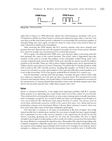
Figure 6.2 PWM and PPM.
right side of Figure 6.2. PPM efficiently utilizes the radio-frequency spectrum with up to
10 channels available in a 20-ms frame in which each channel occupies only a 2-ms slot. I am
sure that even the total frame period is adjusted to accommodate the maximum number of
channels being sent, since again, it makes no sense to waste 10 ms every frame if there are
only 5 channels available to be transmitted.
After receiving the PPM stream, the R/C receiver restores each servo channel and
ensures that each channel has only the required one pulse for every 20-ms period. Modern
R/C receivers usually use a microprocessor to control this process.
PCM is quite a bit different from PPM, since each channel’s data is sent using data bits
that represent the value of the control function. The actual value is dependent upon the
number of bits used to encode the position of the transmitter control being used. Let’s
consider a throttle-stick control in which 10 bits may typically be used to encode the relative
position of the throttle. There are 1024 positive integer numbers that can be represented by
10 bits, which is equivalent to 2 power. Therefore, 0 would be the 0% throttle position, while
10
1023 would be the 100% throttle position. Sending this number via PCM to the receiver
ensures an extremely accurate representation of the equivalent throttle-control position, as it
is set on the transmitter. PCM is the quality method that all reliable R/C systems use.
Not all transmitter controls need this precision. Consider the gear control where only
two values are required, say 0 for gear up and 1 for gear down. It is nonsensical to send
10 bits for this function where 1 bit would suffice. PCM systems are optimized to account for
the transmission of varying channel data precision where some channels require many data
bits for the encoded channel data, while others require only a few.
Noise
Noise, or electrical interference, is the single most important problem with R/C systems.
Noise present in an operating area could easily cause you to lose control of your aircraft.
This could result in you losing the aircraft, or, even worse, causing injury to nearby spectators
and/or damage to property. You would be liable for injury and damages even though you
were not at fault for the interference that caused the loss of control. You always want to
avoid these unfortunate scenarios, which is the reason that some very robust and secure
modulation schemes were developed. Before I discuss these schemes I want to show you
how noise does affect some of the basic modulation techniques.
One item that is common to all types of modulation is the loss of signal. You really
cannot ascribe this to interference; instead, the root cause is simply having a signal strength
that is presented too low at the receiver antenna. A low signal may be caused by several
factors, including operating the aircraft too far from the transmitter. The loss of signal
strength is due to spherical spreading, in other words, the further you are from the transmitter
the more diluted or weakened the signal becomes. Remember this spherical-spreading rule
of thumb (sometimes called the square law): twice the distance from the transmitter means
one quarter of the original signal strength at the receiver. For example, if you had one unit of
strength at a distance of 1 meter from the transmitter, there would be only 1/16,384 of the