
Page 215 - Build Your Own Quadcopter_ Power Up Your Designs with the Parallax Elev-8
P. 215
194 Bu il d Y o ur O w n Q u a d c o p t e r
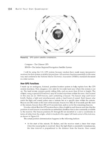
Figure 8.1 GPS system satellite constellation.
Compass—The Chinese GPS
IRNSS—The Indian Regional Navigation Satellite System
I will be using the U.S. GPS system because vendors have made many inexpensive
receivers for that system available for purchase. All receivers function essentially in the same
way and conform to the National Marine Electronics Association (NMEA) standard discussed
in a later section.
how GPS Functions
I made up an analogous, fictional, position-location system to help explain how the GPS
system functions. First, imagine a two-mile by two-mile land area where this system is set
up. The land terrain contains gently rolling hills, each no more than 30 feet in height. The
subject, using a special GPS receiver, may be located anywhere within this area. Also located
in this area are six 100-ft towers, each containing a beacon. The beacon atop each tower
briefly flashes a light and simultaneously emits a loud burst of sound. Each beacon also
emits the light and sound pulses once a minute but at a specific time within the minute.
Beacon one (B1) emits at the start of the minute, beacon two (B2) at 10 seconds past the start
of the minute, beacon three (B3) at 10 seconds later, and so on for the remaining beacons.
It is also critical that the GPS receiver have a line of sight to each beacon and also that the
position of each beacon is recorded in an embedded database that is also constantly available
to the receiver. The beacon positions B1 through B3 are recorded in x and y coordinates in
terms of miles from the origin, which is located in the upper left hand corner of the test area,
as shown in Figure 8.2.
The actual position determination happens in the following fashion:
• At the start of the minute, B1 flashes, and the receiver starts a timer that stops
when the sound pulse is received. Since the light flash is essentially instantaneous,
the time interval is proportional to the distance from the beacon. Since sound