
Page 125 - Build Your Own Transistor Radios a Hobbyists Guide to High-Performance and Low-Powered Radio Circuits
P. 125
RF Antenna Filter Mixer IF Filter 1 IF Amp,jjfier IF Filter 2 IF Amplifier
~ ~ ~ -j ~ r--
/ / / /
VC1 RF/L 1 02 T2 IF Q3 T3 IF 04
/" /1" -1"
f VC'RF AVCVoltage
140 pf Det
/ Low Pass Filter ?- Level Shifter ~ IF Filter 3 ~
" R5C5 " i" T4 IF r-..
Audio Coupling Capacitor C7 =:= 03 D4 R7
Oscillator
Local Oscillator Signal " Audio Amplifier
VC1_ Osc r--
/
05,06,07,08
T1_ Osc/01
l vc10sc
/1 sop,
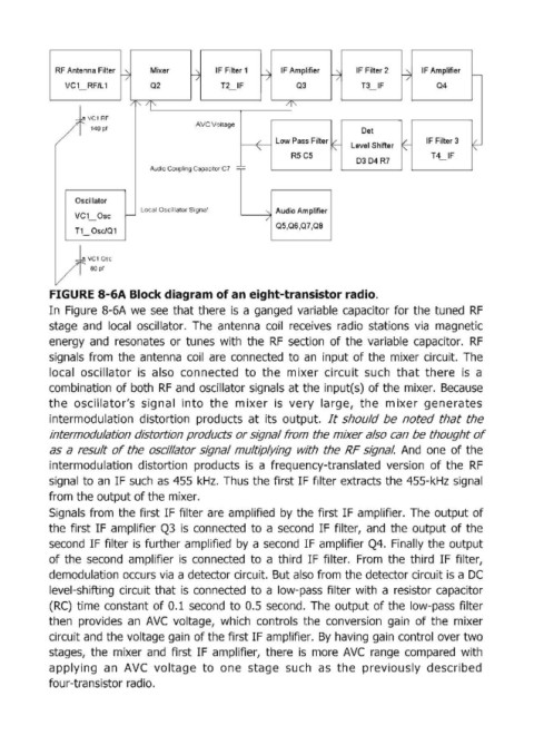
FIGURE 8-6A Block diaglram of an eight-transistor radio.
In Figure 8-6A we see that there is a ganged variable capacitor for the tuned RF
stage and local oscillator. The antenna coil receives radio stations via magnetic
energy and resonates or tunes with the RF section of the variable capacitor. RF
signals from the antenna coil are connected to an input of the mixer circuit. The
local oscillator is also connected to the m ixer circuit such that there is a
combination of both RF and oscillator signals at the input(s) of the mixer. Because
the oscillator's signal into the mixer is very large, the mixer generates
intermodulation distortion products at its output. It should be noted that the
intermodulation distortion products or signal from the mixer also can be thought of
as a result of the oscil/ator signal multiplying with the RF signal. And one of the
intermodulation distortion products is a frequency-translated version of the RF
signa!1 to an IF such as 455 kHz. Thus the first IF filter extracts the 455-kHz signal
from the output of the mixer.
Signals from the first IF filter are amplified by the first IF amplifier. The output of
the first IF amplifier Q3 is connected to a second IF filter, and the output of the
second IF filter is further amplified by a second IF amplifier Q4. Finally the output
of the second amplifier is connected to a third IF filter. From the third IF filter,
demodulation occurs via a detector circuit. But also from the detector circuit is a DC
level-shifting circuit that is connected to a low-pass filter with a resistor capaCitor
(RC) time constant of 0.1 second to 0.5 second. The output of the low-pass filter
then provides an AVC voltage, which controls the conversion gain of the mixer
circuit and the voltage gain of the first IF amplifier. By having gain control over two
stages, the mixer and first IF amplifier, there is more AVC range compared with
applying an AVC voltage to one stage such as the previously described
four-transistor radio.