Page 130 - Build Your Own Transistor Radios a Hobbyists Guide to High-Performance and Low-Powered Radio Circuits
P. 130

.,     "            .,
                                                                + 3  ~I-"--l      421Fl03           R'

                  loop Antenna                                                                      20K
                                                                   T3
                                                                  421Fl02
                                                                     ,.---'--l  Cl<                        coo
                                                                                            '"
                                                                                        0'
                                                                                                     e
                                                            ,--_             2N3904    lN91 4  l N914  T ,   '"
                                                                    II
                                                                              R'    e.           rh,OI  ut
                                                                              'K   .15 ur
            VCI  RF   VCI  RF Pacl   "                                          l
            270 pr   20 pr    421Fl00
                                 r'---Y::
                                                                             e'                        ToVRl
                                      R'                                    .Q1~
                                               C<
                                     4700
                                              ""
                                           .,
             VCIOsc   VCI  Os.t Pad   "                        e,   R'
                         "'.                            ., l33u1            To + 3   6
             60~                           Cl'                    ODK              421Fl00 Pin OUl

                 e"                        ,~
                 33O.                     a'              R'                                 2   ToC3
                     ".    220 uh   e,                    a,                ToOl   4          1   VCI  Dsc
                     e"     co             2N3904         3300


                                                 e2
                                         R2  '001         lN914                     Bottom View
                                  .01  uI                 D2
                                         lK---> 500       lN914          "-------'7 To R1210K


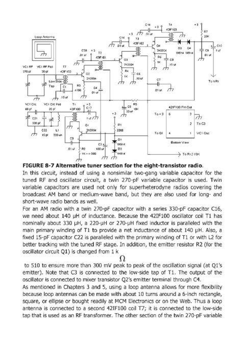
            FIGURE 8-7 Alternative tuner section for the eight-transistor radio.
            In  this  circuit,  instead  of using  a  nonsimilar  two-gang  variable  capacitor  for  the
            tuned  RF  and  oscillator  circuit,  a twin  270-pF  variable  capacitor  is  used.  Twin
            variable  capacitors  are  used  not  only  for  superheterodyne  radios  covering  the
            broadcast  AM  band  or  medium-wave  band,  but  they  are  also  used  for  long- and

            short-wave radio bands as well.
            For  an  AM  radio  with  a twin  270-pF  capacitor  with  a series  330-pF  capacitor  C16,
            we  need  about  140  ~H of inductance.  Because  the  42IF100  oscillator  coil  T1  has
            nominally about  330  ~H, a  220-~H or  270-~H fixed  inductor  is  paralleled  with  the
            main  primary winding  of T1  to provide  a net  inductance  of about  140  ~H. Also,  a

            fixed  15-pF capacitor C22  is paralleled with the  primary winding of T1  or with  L2 for
            better tracking with the tuned RF stage.  In addition, the emitter resistor R2  (for the
            oscillator circuit Q1)  is changed from  1 k
                                                           n

             to 510  to ensure  more than  300  mV  peak to peak  of the  oscillation Signal  (at Q1's
            emitter).  Note  that C3  is  connected  to  the  low-side  tap  of Tl. The  output of the
            oscillator is connected to mixer transistor Q2's emitter terminal through C4.

            As  mentioned  in  Chapters  3 and  5,  using  a loop  antenna allows for more flexibility
            because loop antennas can  be made with about 10 turns around a 6-inch  rectangle,
            square,  or ellipse or bought readily at MCM  Electronics or on  the Web.  Thus a loop
            antenna  is  connected  to a second  42IF100  coil  T7;  it is  connected  to the  low-side
            tap that is used as  an  RF  transformer. The other section of the twin  270-pF variable
   125   126   127   128   129   130   131   132   133   134   135