
Page 135 - Build Your Own Transistor Radios a Hobbyists Guide to High-Performance and Low-Powered Radio Circuits
P. 135
"First" Design of a Low-Power Superheterodyne Radio
Actually, the real first design was built a couple of years ago with a current drain of
about 140 J.lA for five years of continuous service on a single C cell. This radio was
mentioned in EDN Magazine on the web in October of 2011
(www.edn.com/blog/Designing_Ideas/41377-A_super_het_radio_runs_S_years_on_
a_C_cell_plus_a_ pentode_radio.php). But the "first" design for this book is a
refined version based on the radio just mentioned that features even lower power.
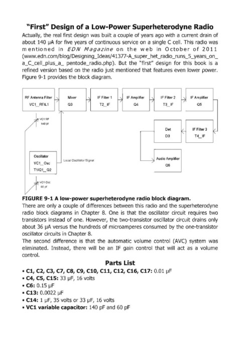
Figure 9-1 provides the block diagram.
RF Antenna Filter Mixer IF Filter 1 IF Amplifier IF Filter 2 IF Amplifier
~ ~ ~ ~ ~ r--
/ / / / /
VC 1_ RF/L 1 Q3 T2_ IF Q4 T3_ IF Q5
/"-
/k 140pt
.....,~ VC1 RF
Det IF Filter 3
~ ~
D3 T4 IF
Oscillator
Local Oscillator Signal "- Audio Amplifier
VC1_ OSC r- /
Q6
T1/Q1_ Q2
1 VC 1 Dsc
f 60pf
F GURE 9-1 A low-power superheterodyne radio block diagram.
There are only a couple of differences between this radio and the superheterodyne
radio block diagrams in Chapter 8. One is that the oscillator circuit requires two
transistors instead of one. However, the two-transistor oscillator circuit drains only
about 36 J.lA versus the hundreds of microamperes consumed by the one-transistor
oscillator circuits in Chapter 8.
The second difference is that the automatic volume control CAVC) system was
eliminated. Instead, there will be an IF gain control that will act as a volume
control.
Parts List
• Cl, C2, C3, C7, CS, C9, ClO, ell, Cl2, Cl6,Cl7: 0.01 J.lF
• C4, CS, Cl5: 33 J.lF, 16 volts
• C6: 0.15 IJF
• Cl3: 0.0022 IJF
• Cl4: 1 J.lF, 35 volts or 33 J.lF, 16 volts
• VCl variable capacitor: 140 pF and 60 pF