Page 137 - Build Your Own Transistor Radios a Hobbyists Guide to High-Performance and Low-Powered Radio Circuits
P. 137

+  1.5
                                                                                 .01  ut
                                                                 +  1.5                     "
                                                                                           421Fl01
            VCl RF   VCl RF Pad                                                                          Re
                                                                                             11[          lOOK
            140 pI    20 pf                                                                        C13
                                          C7   +  1.5                          MPSH10              0022 ut
                                                  T2                                        D3
                         nl  · ll Primary   .01  ut
                         11                      421Fl0l                        R7    CI2
                              680 U: Mp~~~~==lIIC
                                   3                                            12K 1" ~  '""           R9
                                                                                              Cl<       UM
                                                               R6
                         m . l~u~eCOndary  R5  1----,   R13    12K                            l~
                                                                            R"
                                                                                                    +  1.5
                                              C6      lOOK                  lOOK
                                      12K         T
                                             .15Ul
                                                 m
                                                                                                      R12
                 VCl OscVCl  Osc Pad                                                          Rll     56K
                                                   +  1.5       +  1.5
                 60 pf   20 pf                           C<
                                                         33~                         RlD                  f-
                                             C2                      R'                       '"        C15
                                            ''''             R3      56K              lOOK      06      33~
                                                                               ClD            2N5089
                               Cl         Ol    02           56K
                                        MPSH 1 0  MPSH 1 0                     ,,~
                                             C3                      Dl
                                                           C5        lN914
             Note #  1: Capacitor Removed                            D2       Note # 2:  Use Low Side Tap forT2,T3 & T4
             From Tl,  421Fl03; vel_Ost   RI   .01  of   R2   33~1
                                                                     lN914
             to High Side Tap ofTl.   12K             12K


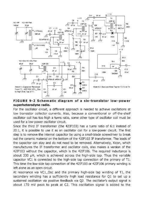
            FIGURE  9-2  Schematic  diagram  of a  six-transistor  low-power
            superheterodyne radio.
            For  the  oscillator  circuit,  a different approach  is  needed  to  achieve  oscillations  at
            low  transistor  collector  currents.  Also,  because  a  conventional  or  off-the-shelf
            oscillator coil  has too  high  a turns  ratio, some  other type  of oscillator coil  must  be
            used for a low-power oscillator circuit.

            Since  the  third  IF  transformer  (the  42IF103)  has  a turns  ratio  of 6: 1 instead  of
            20:1,  it is  possible  to  use  it  as  an  oscillator  coil for  a low-power circuit.  The first
            step is to remove  the internal capacitor by using a small-blade  screwdriver to break
            out the ceramic material on  the bottom of the 42IF103 IF transformer. The leads of
            the capacitor  can  stay and  do  not need  to  be  removed.  Alternatively,  Xicon,  which

            manufactures  the  IF transformer  and  oscillator  coils,  also  makes  a version  of the
            42IF103  without  the  capacitor,  which  is  the  42IF106.  The  required  inductance  is
            about  330  ~H, which  is  achieved  across  the  high-side  tap.  Thus  the  variable
            capacitor  Vcl  is  connected  to the  high-side  tap  connection  of the  primary  of Tl.
            This time the low-side tap connection of the 42IF103 or 42IF106 primary winding  is
            left alone as an open circuit.

            At  resonance  via  VC1_0sc  and  the  primary  high-side  tap  winding  of Tl,  the
            secondary  winding  has  a  sufficiently  high  load  resistance  for  Q1  to  set  up  a
            sustained  oscillation  via  positive  feedback  via  Q2. The  oscillator's  output  signal  is
            about  170  mV  peak  to  peak  at  C2.  This  oscillation  signal  is  added  to  the
   132   133   134   135   136   137   138   139   140   141   142