
Page 132 - Build Your Own Transistor Radios a Hobbyists Guide to High-Performance and Low-Powered Radio Circuits
P. 132
Thus the output signal from Q2's collector into the IF filter, T2, is a 4S5-kHz AM
signal.
The AVC voltage from CS is sent to the base of Q2 via resistor R20 and to the base
of the IF amplifier transistor Q3 via the secondary winding of the second IF
transformer T2 (42IF102). As we will see in Chapter 9, the differential-pair oscillator
will play an important role in low-powered oscillator circuits.
T4 +3
R7
Loop Antenna 20K
C10
C20 1 uf
T2 lN9 14 1N914
VCl RF VC1 RF PaCl T7
270 pr 20 pr
C7 ToVR1
.01~
VCl0sc
R18 56K +3 +3 R5
C17 CS
1U~ J33uf 10K
C1 RI
r--1
15 pr
01
Note: C22 m C23
is optional lN914
.01 uf
02
lN914 t-------------7 To R12 10K
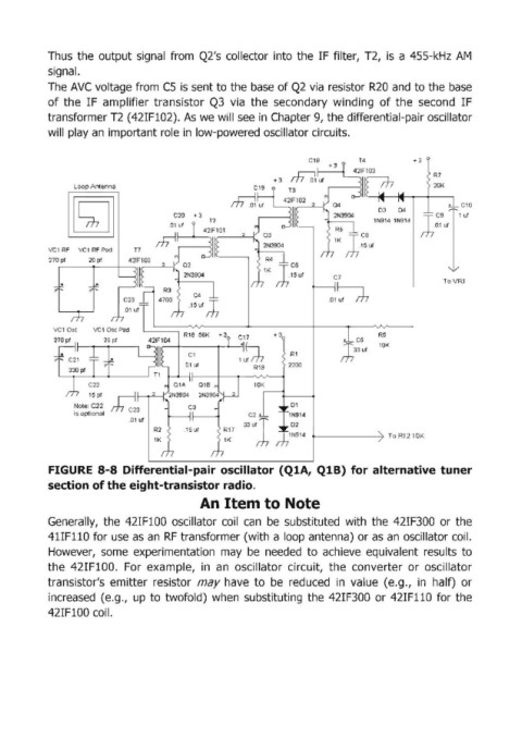
FIGURE S-SDifferential-pair oscillator (Q1A, Q1B) for alternative tuner
section of the eight-transistor radio.
An Item to Note
Generally, the 42IFIOO oscillator coil can be substituted with the 42IF300 or the
41IF110 for use as an RF transformer (with a loop antenna) or as an oscillator coil.
However, some experimentation may be needed to achieve equivalent results to
the 42IFIOO. For example, in an oscillator circuit, the converter or oscillator
transistor's emitter resistor may have to be reduced in value (e.g., in half) or
increased (e.g., up to twofold) when substituting the 42IF300 or 421FII0 for the
42IFI00 coil.