
Page 128 - Build Your Own Transistor Radios a Hobbyists Guide to High-Performance and Low-Powered Radio Circuits
P. 128
C12 .,
~20uf TO
Q7 2N3904
.3
C16
Audio Out
T4
R14 liS
, 220 ut
RlO 11
ToCl0 4700 Audio DIV.
C12 08 2N3904
0'
R' "
2N3904 .,
220 ut R13
lOOK
R12 2200
"'" CII Re lOK R11 C14
lOOK 05 '" 220 ut 05
20K 2N3904
1", C15 lN914
,,"' 0'
lN270
To Dl/C2 (Dl Anode)
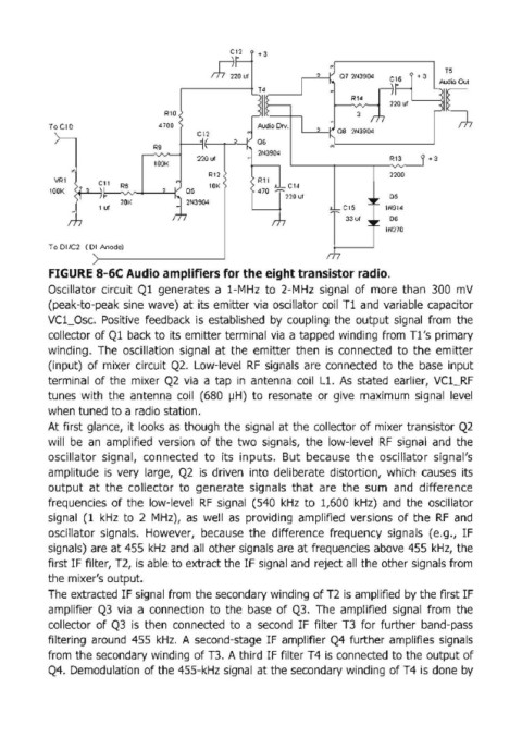
FIGURE 8-6C Audio amplifiers for the eight transistor radio.
Oscillator circuit Q1 generates a 1-MHz to 2-MHz signal of more than 300 mV
(peak-to-peak sine wave) at its emitter via oscillator coil T1 and variable capacitor
Vcl_Osc. Positive feedback is established by coupling the output signal from the
collector of Q1 back to its emitter terminal via a tapped winding from T1 's primary
winding. The oscillation signal at the emitter then is connected to the emitter
(input) of mixer circuit Q2. Low-level RF signals are connected to the base input
terminal of the mixer Q2 via a tap in antenna coil Ll. As stated earlier, VC1_RF
tunes with the antenna coil (680 IJH) to resonate or give maximum signal level
when tuned to a radio station.
At first glance, it looks as though the signal at the collector of mixer transistor Q2
will be an amplified version of the two signals, the low-level RF signal and the
oscillator signal, connected to its inputs. But because the oscillator signal's
amplitude is very large, Q2 is driven into deliberate distortion, which causes its
output at the collector to generate signals that are the sum and difference
frequencies of the low-level RF signal (540 kHz to 1,600 kHz) and the oscillator
signal (1 kHz to 2 MHz), as well as providing amplified versions of the RF and
oscillator signals. However, because the difference frequency signals (e.g., IF
signals) are at 455 kHz and all other signals are at frequencies above 455 kHz, the
first IF filter, T2, is able to extract the IF signal and reject all the other signals from
the mixer's output.
The extracted IF signal from the secondary winding of T2 is amplified by the first IF
amplifier Q3 via a connection to the base of Q3. The amplified signal from the
collector of Q3 is then connected to a second IF filter T3 for further band-pass
filtering around 455 kHz. A second-stage IF amplifier Q4 further amplifies signals
from the secondary winding of n. A third IF filter T4 is connected to the output of
Q4. Demodulation of the 455-kHz signal at the secondary winding of T4 is done by