
Page 127 - Build Your Own Transistor Radios a Hobbyists Guide to High-Performance and Low-Powered Radio Circuits
P. 127
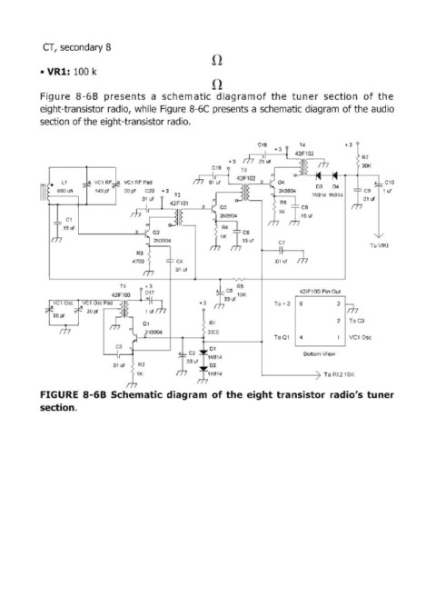
CT,  secondary 8


            • VR1:  100 k


            Figu re  8-6B  presents  a  schem atic  d iag ra m of  the  tuner  section  of  the
            eight-transistor radio,  while Figure  8-6C  presents a schematic diagram of the audio
            section of the eight-transistor radio.


                                                                                                    R7
                                                                                                    20K

               •   L1      VCl  RF   VCl  RF Pad                                                           Cl0
            111   680 uh   140 pr   20 pt   C20   + 3                                  1N914  1N914   T  C9   1 ut
                                                                                                 m   ,01ut

                   Cl

               l'5'" '-----------""0.........{
                                                                             C7                        ToVR1
                                                                            .01~


                                                                  R5
                                                               C5                  421F100 Pin Out
                                                                  10K
                                                        +3   J33ut          To + 3   6       3

                                                                                             2   ToC3
                                                          RI
                                                                            To01   4             vel0sc
                                                           01
                                                                                    Bottom View
                                                          1N914
                                .01  ut                    02
                                                          lN914                           To R1210K

            FIGURE  8-68 Schematic diagram  of the  eight transistor  radio's  tuner
            section.