
Page 175 - Buried Pipe Design
P. 175
Design of Gravity Flow Pipes 149
Angular Coordinates
of Circular Pipe
Soil Material
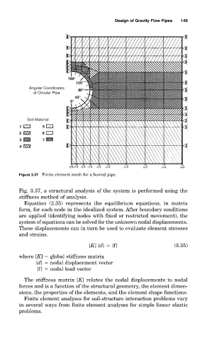
Figure 3.37 Finite element mesh for a buried pipe.
Fig. 3.37, a structural analysis of the system is performed using the
stiffness method of analysis.
Equation (3.35) represents the equilibrium equations, in matrix
form, for each node in the idealized system. After boundary conditions
are applied (identifying nodes with fixed or restricted movement), the
system of equations can be solved for the unknown nodal displacements.
These displacements can in turn be used to evaluate element stresses
and strains.
[K] {d} {f} (3.35)
where [K] global stiffness matrix
{d} nodal displacement vector
{f} nodal load vector
The stiffness matrix [K] relates the nodal displacements to nodal
forces and is a function of the structural geometry, the element dimen-
sions, the properties of the elements, and the element shape functions.
Finite element analyses for soil-structure interaction problems vary
in several ways from finite element analyses for simple linear elastic
problems.