
Page 302 - Buried Pipe Design
P. 302
Rigid Pipe Products 273
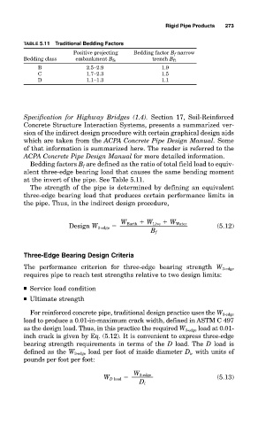
TABLE 5.11 Traditional Bedding Factors
Positive projecting Bedding factor B f narrow
Bedding class embankment B fe trench B ft
B 2.5–2.9 1.9
C 1.7–2.3 1.5
D 1.1–1.3 1.1
Specification for Highway Bridges (1.4). Section 17, Soil-Reinforced
Concrete Structure Interaction Systems, presents a summarized ver-
sion of the indirect design procedure with certain graphical design aids
which are taken from the ACPA Concrete Pipe Design Manual. Some
of that information is summarized here. The reader is referred to the
ACPA Concrete Pipe Design Manual for more detailed information.
Bedding factors B f are defined as the ratio of total field load to equiv-
alent three-edge bearing load that causes the same bending moment
at the invert of the pipe. See Table 5.11.
The strength of the pipe is determined by defining an equivalent
three-edge bearing load that produces certain performance limits in
the pipe. Thus, in the indirect design procedure,
W Earth W Live W Water
Design W 3-edge (5.12)
B f
Three-Edge Bearing Design Criteria
The performance criterion for three-edge bearing strength W 3-edge
requires pipe to reach test strengths relative to two design limits:
■ Service load condition
■ Ultimate strength
For reinforced concrete pipe, traditional design practice uses the W 3-edge
load to produce a 0.01-in-maximum crack width, defined in ASTM C 497
as the design load. Thus, in this practice the required W 3-edge load at 0.01-
inch crack is given by Eq. (5.12). It is convenient to express three-edge
bearing strength requirements in terms of the D load. The D load is
defined as the W 3-edge load per foot of inside diameter D i , with units of
pounds per foot per foot:
W 3-edge
W D load (5.13)
D i