
Page 297 - CNC Robotics
P. 297
Chapter 12 / Examples
bolted to a sq uare of MDF, with holes for screws to attach it to th e
wood to be tu rned . The dr iven end of the material is screwed to a
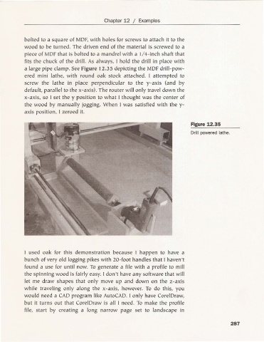
piec e of MDF tha t is bolted to a ma ndrel wit h a 1/4-inch shaft that
fits the ch uck of the drill. As always, I hold the drill in place with
a large pipe clamp. See Figure 12.35 de picting the MDF drill-pow-
ered mini lathe, with round oak stock attached. I attempted to
sc rew the lathe in place perpendicular to the y-ax is (and by
default, para llel to the x-axis). The router will only travel down the
x-axis, so I se t the y position to what I thought was the cen ter of
the wood by manually jogging. Wh en I was satisfied with the y-
ax is position , I ze roed it.
Figure 12.35
Drill powered lathe.
I used oak for this demonstration because I happen to ha ve a
bunch of very old logging pikes with 20-foot handles that I haven't
fou nd a use for until now. To generate a file with a profile to mill
the spinning wood is fairly easy. I don't have any software that will
let me draw shapes that only move up a nd down on the z-ax is
while trave ling only along the x-ax is, however. To do thi s, you
would need a CAD program like AutoCAD. I on ly have CorelDraw,
but it turn s out th at CorelDraw is all I need. To make the profile
file, sta rt by creating a long narrow page set to lands cape in
287