
Page 106 - Cam Design Handbook
P. 106
THB4 8/15/03 1:01 PM Page 94
94 CAM DESIGN HANDBOOK
Displacement
Dwell
Velocity
y, y', y'', y'''
Dwell
Cam angle q
Jerk Acceleration
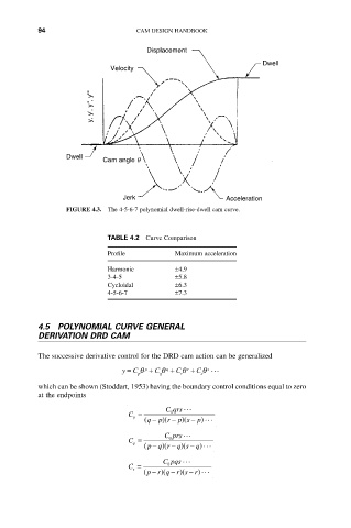
FIGURE 4.3. The 4-5-6-7 polynomial dwell-rise-dwell cam curve.
TABLE 4.2 Curve Comparison
Profile Maximum acceleration
Harmonic ±4.9
3-4-5 ±5.8
Cycloidal ±6.3
4-5-6-7 ±7.3
4.5 POLYNOMIAL CURVE GENERAL
DERIVATION DRD CAM
The successive derivative control for the DRD cam action can be generalized
s
y = C q p + C q q + C q r + C q ...
q
p
r
s
which can be shown (Stoddart, 1953) having the boundary control conditions equal to zero
at the endpoints
C qrs ...
C = 0
p ( q - ) - ) - p) ...
p r (
p s (
C prs ...
C = 0
q ( pq r q s q) ...
(
(
- ) - ) -
C pqs ...
C = 0
r ( pr q r s r) ...
- )(
- ) -
(