
Page 174 - Cam Design Handbook
P. 174
THB6 8/15/03 2:40 PM Page 162
162 CAM DESIGN HANDBOOK
6.3 CAM PRESSURE ANGLE
6.3.1 Introduction
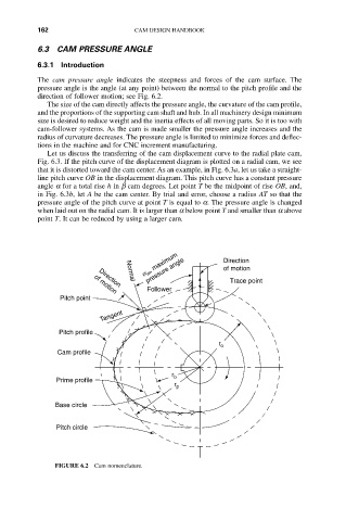
The cam pressure angle indicates the steepness and forces of the cam surface. The
pressure angle is the angle (at any point) between the normal to the pitch profile and the
direction of follower motion; see Fig. 6.2.
The size of the cam directly affects the pressure angle, the curvature of the cam profile,
and the proportions of the supporting cam shaft and hub. In all machinery design minimum
size is desired to reduce weight and the inertia effects of all moving parts. So it is too with
cam-follower systems. As the cam is made smaller the pressure angle increases and the
radius of curvature decreases. The pressure angle is limited to minimize forces and deflec-
tions in the machine and for CNC increment manufacturing.
Let us discuss the transferring of the cam displacement curve to the radial plate cam,
Fig. 6.3. If the pitch curve of the displacement diagram is plotted on a radial cam, we see
that it is distorted toward the cam center. As an example, in Fig. 6.3a, let us take a straight-
line pitch curve OB in the displacement diagram. This pitch curve has a constant pressure
angle a for a total rise h in b cam degrees. Let point T be the midpoint of rise OB, and,
in Fig. 6.3b, let A be the cam center. By trial and error, choose a radius AT so that the
pressure angle of the pitch curve at point T is equal to a. The pressure angle is changed
when laid out on the radial cam. It is larger than a below point T and smaller than a above
point T. It can be reduced by using a larger cam.
a m , maximum Direction
pressure angle
of motion
Normal
Direction
Follower Trace point
of motion
Pitch point
Tangent
Pitch profile
r o
Cam profile
r b
Prime profile
r p
Base circle
Pitch circle
FIGURE 6.2 Cam nomenclature.