
Page 178 - Cam Design Handbook
P. 178
THB6 8/15/03 2:40 PM Page 166
166 CAM DESIGN HANDBOOK
1
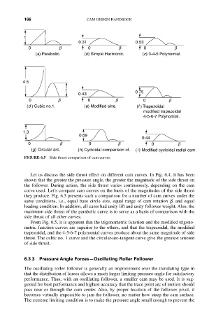
0.31 0.53
0 b 0 b 0 b
(a) Parabolic. (b) Simple Harmonic. (c) 3-4-5 Polynomial.
4.5
1 0.75
0.43
0 b 0 b 0 b
(d ) Cubic no.1. (e) Modified sine. (f ) Trapezoidal
modified trapezoidal
4-5-6-7 Polynomial.
1.3
0.69
0.44
0 b 0 b 0 b
(g) Circular arc. (h) Cycloidal comparison of. ( i ) Modified cycloidal radial cam.
FIGURE 6.5 Side thrust comparison of cam curves.
Let us discuss the side thrust effect on different cam curves. In Fig. 6.4, it has been
shown that the greater the pressure angle, the greater the magnitude of the side thrust on
the follower. During action, the side thrust varies continuously, depending on the cam
curve used. Let’s compare cam curves on the basis of the magnitudes of the side thrust
they produce. Fig. 6.5 presents such a comparison for a number of cam curves under the
same conditions, i.e., equal base circle size, equal range of cam rotation b, and equal
loading condition. In addition, all cams had unity lift and unity follower weight. Also, the
maximum side thrust of the parabolic curve is to serve as a basis of comparison with the
side thrust of all other curves.
From Fig. 6.5, it is apparent that the trigonometric function and the modified trigono-
metric function curves are superior to the others, and that the trapezoidal, the modified
trapezoidal, and the 4-5-6-7 polynomial curves produce about the same magnitude of side
thrust. The cubic no. 1 curve and the circular-arc-tangent curve give the greatest amount
of side thrust.
6.3.3 Pressure Angle Forces—Oscillating Roller Follower
The oscillating roller follower is generally an improvement over the translating type in
that the distribution of forces allows a much larger limiting pressure angle for satisfactory
performance. Thus, with an oscillating follower, a smaller cam may be used. It is sug-
gested for best performance and highest accuracy that the trace point arc of motion should
pass near or through the cam center. Also, by proper location of the follower pivot, it
becomes virtually impossible to jam the follower, no matter how steep the cam surface.
The extreme limiting condition is to make the pressure angle small enough to prevent the