
Page 175 - Cam Design Handbook
P. 175
THB6 8/15/03 2:40 PM Page 163
ELEMENTS OF CAM PROFILE GEOMETRY 163
Less than
a
a Pitch curve B
Normal
a
B
Midpoint, T h
Total rise, h Midpoint, T More than a
h/2
Pitch curve
O
O b
Cam angle b
A
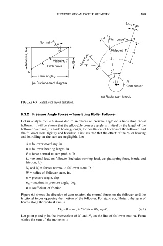
(a) Displacement diagram.
Cam center
(b) Radial cam layout.
FIGURE 6.3 Radial cam layout distortion.
6.3.2 Pressure Angle Forces—Translating Roller Follower
Let us analyze the side thrust due to an excessive pressure angle on a translating radial
follower. It will be shown that the allowable pressure angle is limited by the length of the
follower overhang, its guide bearing length, the coefficient of friction of the follower, and
the follower stem rigidity and backlash. First assume that the effect of the roller bearing
and its rolling on the cam are negligible. Let
A = follower overhang, in
B = follower bearing length, in
F = force normal to cam profile, lb
L o = external load on follower (includes working load, weight, spring force, inertia and
friction, lb)
N 1 and N 2 = forces normal to follower stem, lb
W = radius of follower stem, in.
a = pressure angle, deg
a m = maximum pressure angle, deg
m = coefficient of friction
Figure 6.4 shows the direction of cam rotation, the normal forces on the follower, and the
frictional forces opposing the motion of the follower. For static equilibrium, the sum of
forces along the vertical axis is
0
F
SF == - L + cosa - m N - m N . (6.1)
y 0 1 2
Let point p and q be the intersection of N 1 and N 2 on the line of follower motion. From
statics the sum of the moments is