Page 179 - Cam Design Handbook
P. 179

THB6  8/15/03  2:40 PM  Page 167

                               ELEMENTS OF CAM PROFILE GEOMETRY            167

            cam normal force from passing through the follower pivot. Locking results from this detri-
            mental force distribution. Often, for ultimate performance, frequent trials must be made
            to determine the performance and establish the best dimensional proportions for the given
            design conditions. Therefore, the side thrust will not exist with the properly designed oscil-
            lating roller follower in which the maximum pressure angle is much smaller than a locking
            condition.
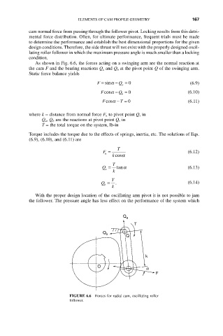
               As shown in Fig. 6.6, the forces acting on a swinging arm are the normal reaction at
            the cam F and the bearing reactions Q a and Q b at the pivot point Q of the swinging arm.
            Static force balance yields

                                       F = sina  -  Q = 0                  (6.9)
                                                a
                                        Fcosa - Q = 0                     (6.10)
                                                b
                                         Fcosa - T = 0                    (6.11)

            where k = distance from normal force F n to pivot point Q, in
                 Q a, Q b are the reactions at pivot point Q, in
                 T = the total torque on the system, lb-in
            Torque includes the torque due to the effects of springs, inertia, etc. The solutions of Eqs.
            (6.9), (6.10), and (6.11) are
                                              T
                                         F =                              (6.12)
                                          n
                                            k cosa
                                            T
                                        Q =   tana                        (6.13)
                                          a
                                             k
                                            T
                                        Q =   .                           (6.14)
                                         b
                                            k
               With the proper design location of the oscillating arm pivot it is not possible to jam
            the follower. The pressure angle has less effect on the performance of the system which


                                                 Q a
                                                     T
                                         Q b
                                                  Q


                                                         k

                                       O
                                                          a
                                                             F


                            FIGURE 6.6  Forces for radial cam, oscillating roller
                            follower.
   174   175   176   177   178   179   180   181   182   183   184