
Page 430 - Cam Design Handbook
P. 430
THB13 9/19/03 7:56 PM Page 418
418 CAM DESIGN HANDBOOK
k s c
y
m o
k f l b
l ao
y c
m f
Cam
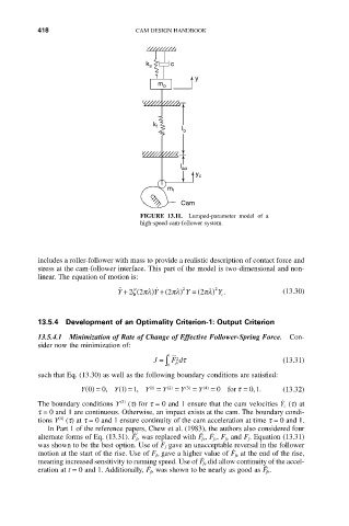
FIGURE 13.11. Lumped-parameter model of a
high-speed cam-follower system.
includes a roller-follower with mass to provide a realistic description of contact force and
stress at the cam-follower interface. This part of the model is two-dimensional and non-
linear. The equation of motion is:
˙˙
˙
(
Y + 22zpl Y ) + (2pl ) 2 Y = (2pl ) 2 Y . (13.30)
c
13.5.4 Development of an Optimality Criterion-1: Output Criterion
13.5.4.1 Minimization of Rate of Change of Effective Follower-Spring Force. Con-
sider now the minimization of:
1
J = F dt (13.31)
˙˙˙2
Ú 0 fe
such that Eq. (13.30) as well as the following boundary conditions are satisfied:
Y 0 () = 0, Y 1 () = 1, Y 1 () = Y 2 ( ) = Y 3 ( ) = Y 4 ( ) = 0 for t = 0 1. (13.32)
,
.
The boundary conditions Y (3) (t) for t = 0 and 1 ensure that the cam velocities Y c (t) at
t = 0 and 1 are continuous. Otherwise, an impact exists at the cam. The boundary condi-
(4)
tions Y (t) at t = 0 and 1 ensure continuity of the cam acceleration at time t = 0 and 1.
In Part 1 of the reference papers, Chew et al. (1983), the authors also considered four
.
...
¨
alternate forms of Eq. (13.31). F fe was replaced with F fe, F fc, F fe and F f. Equation (13.31)
was shown to be the best option. Use of F f gave an unacceptable reversal in the follower
.
motion at the start of the rise. Use of F fe gave a higher value of F fe at the end of the rise,
¨
meaning increased sensitivity to running speed. Use of F fe did allow continuity of the accel-
.
¨
eration at t = 0 and 1. Additionally, F fe was shown to be nearly as good as F fe.