
Page 437 - Cam Design Handbook
P. 437
THB13 9/19/03 7:56 PM Page 425
CAM SYSTEM DYNAMICS—RESPONSE 425
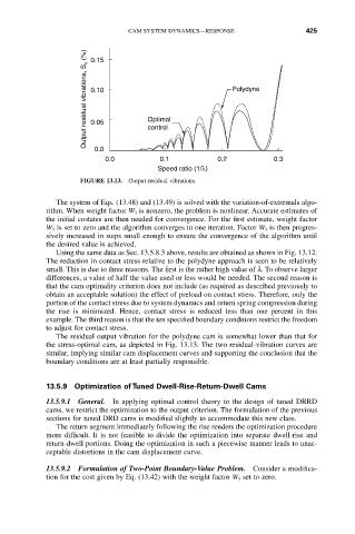
Output residual vibrations, S v (%) 0.10 Optimal Polydyne
0.15
0.05
0.0 control
0.0 0.1 0.2 0.3
Speed ratio (1/l)
FIGURE 13.13. Output residual vibrations.
The system of Eqs. (13.48) and (13.49) is solved with the variation-of-extremals algo-
rithm. When weight factor W 3 is nonzero, the problem is nonlinear. Accurate estimates of
the initial costates are then needed for convergence. For the first estimate, weight factor
W 3 is set to zero and the algorithm converges in one iteration. Factor W 3 is then progres-
sively increased in steps small enough to ensure the convergence of the algorithm until
the desired value is achieved.
Using the same data as Sec. 13.5.8.3 above, results are obtained as shown in Fig. 13.12.
The reduction in contact stress relative to the polydyne approach is seen to be relatively
small. This is due to three reasons. The first is the rather high value of l. To observe larger
differences, a value of half the value used or less would be needed. The second reason is
that the cam optimality criterion does not include (as required as described previously to
obtain an acceptable solution) the effect of preload on contact stress. Therefore, only the
portion of the contact stress due to system dynamics and return spring compression during
the rise is minimized. Hence, contact stress is reduced less than one percent in this
example. The third reason is that the ten specified boundary conditions restrict the freedom
to adjust for contact stress.
The residual output vibration for the polydyne cam is somewhat lower than that for
the stress-optimal cam, as depicted in Fig. 13.13. The two residual-vibration curves are
similar, implying similar cam displacement curves and supporting the conclusion that the
boundary conditions are at least partially responsible.
13.5.9 Optimization of Tuned Dwell-Rise-Return-Dwell Cams
13.5.9.1 General. In applying optimal control theory to the design of tuned DRRD
cams, we restrict the optimization to the output criterion. The formulation of the previous
sections for tuned DRD cams is modified slightly to accommodate this new class.
The return segment immediately following the rise renders the optimization procedure
more difficult. It is not feasible to divide the optimization into separate dwell-rise and
return-dwell portions. Doing the optimization in such a piecewise manner leads to unac-
ceptable distortions in the cam displacement curve.
13.5.9.2 Formulation of Two-Point Boundary-Value Problem. Consider a modifica-
tion for the cost given by Eq. (13.42) with the weight factor W 3 set to zero.