Page 442 - Cam Design Handbook
P. 442
THB13  9/19/03  7:56 PM  Page 430

          430                      CAM DESIGN HANDBOOK

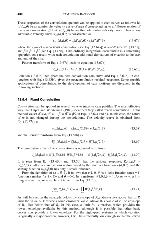
          These properties of the convolution operator can be applied to cam curves as follows: let
          v i (d,b,q) be an admissible velocity curve of area d corresponding to a follower motion of
          rise d in cam rotation b. Let w(d,b,q) be another admissible velocity curve. Then a new
          admissible velocity curve v i+1 (d,b,q) is constructed as
                                       v d¢¢ )* (
                              v ( d,,bq ) = ( , ,b q  w d¢¢ ¢¢ )      (13.67a)
                                                       ,q
                                                    ,b
                                        i
                              i+1
          where the symbol  * represents convolution (see Eq. [13.64a]) d = d¢d≤ (see Eq. [13.65])
          and b = b¢+ b≤ (see Eq. [13.66]). Like ordinary integration, convolution is a smoothing
          operation. As a result, with each convolution additional derivatives of v vanish at the start
          and end of the rise.
             Fourier transform of Eq. (13.67a) leads to equation (13.67b)
                                               ◊ (
                                       V d¢¢ )
                             V ( d,, k) = ( , , k W d¢¢ ¢¢, k).       (13.67b)
                                                     b
                                  b
                                           b
                                                    ,
                              i+1       i
          Equation (13.67a) then gives the post convolution cam curve and Eq. (13.67b), in con-
          junction with Eq. (13.63b), gives the postconvolution residual response. Some specific
          applications  of  convolution  to  the  development  of  cam  motions  are  discussed  in  the
          following sections.
          13.6.4 Fixed Convolution
          Convolution can be applied in several ways to improve cam profiles. The most effective
          way that Gupta and Wiederrich (1983) identified they called fixed convolution. In this
          method we set d¢= d, d≤= 1, b¢= b≤= b/2 in Eqs. (13.67a and b). In this case, the nature
          of  w is  not  changed  during  the  convolutions.  The  velocity  curve  is  obtained  from
          Eq. (13.67a) as
                                  b
                             v ( d, ,q ) =  v d ( ,b  2,q )*  w(1,b  2,q )  (13.68)
                              i+1       i
          and the Fourier transform from Eq. (13.67b) as
                             V ( d, , k) = (  2, k W(1,b  2, k).       (13.69)
                                               )
                                       V d,b
                                                ◊
                                  b
                              i+1
                                        i
          The cumulative effect of m convolutions is obtained as follows:
                    (
                      b
                                                        k V d,b 2
                                  k W ,b 4
                                                W ,b 2
                           W ,b 2
                  Vd, , k) = (1   , ) ◊ ( 1  k , ) ◊◊◊ (1  m , ) ◊ (  m  k , . )  (13.70)
                   m                                        0
          It  is  seen  from  Eq.  (13.63b)  and  (13.70)  that  the  residual  response,  R m(d,b,k)  =
          |V m (d,b,k)|, after m convolutions is dominated by the modifier function w(d,b,q), and the
          starting function v 0(d,b,q) has only a small influence.
             From the definition of v(1, b, q), it follows that v(1, 0, q) is a delta function (area = 1,
          function vanishes for q < 0- and q > 0+). Its transform |V(1,0,k,)| = 1. As m Æ•, a lim-
          iting residual response is thus obtained from Eq. (13.70).
                                             •
                             lim Rd (  , ,k) =  d ◊ ’ W(1 ,b 2  r ,k)  (13.71)
                                     b
                             m Æ•  m
                                            r=1
          As will be seen in the example below, the envelope of R i+1 always lies above that of R i
          until the value of k exceeds some crossover value. Above this value of k, the envelope
          of  R i+1 lies  below  that  of  R i .  In  this  case,  a  limit  R • is  reached  which  provides  the
          lowest  envelope  available  by  this  method,  although  it  is  possible  that  other  basic
          curves  may  provide  a  lower  envelope.  For  the  high-speed  systems  in  which  vibration
          is typically a major concern, however, k will be sufficiently low enough so that the lowest

