
Page 446 - Cam Design Handbook
P. 446
THB13 9/19/03 7:56 PM Page 434
434 CAM DESIGN HANDBOOK
log R*(K)
0
-1
-2
1
0 (simple harmonic)
8
-3
1 (cycloidal)
2
-4 K
0 4 p 8 p 12 p 16 p 20 p
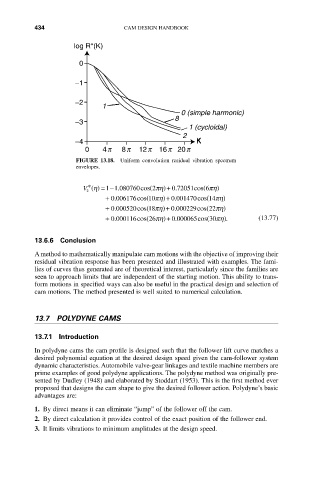
FIGURE 13.18. Uniform convolution residual vibration spectrum
envelopes.
V * h () =- . 2ph)+ 0 72051cos( 6ph)
.
1 1 080760cos(
2
.
+ 0 006176cos( 10ph)+ 0 001470cos( 14ph)
.
+ 0 000520cos( 18ph)+ 0 000229cos( 22ph)
.
.
+ 0 000116cos( 26ph)+ 0 000065cos( 30ph) . (13.77)
.
.
13.6.6 Conclusion
A method to mathematically manipulate cam motions with the objective of improving their
residual vibration response has been presented and illustrated with examples. The fami-
lies of curves thus generated are of theoretical interest, particularly since the families are
seen to approach limits that are independent of the starting motion. This ability to trans-
form motions in specified ways can also be useful in the practical design and selection of
cam motions. The method presented is well suited to numerical calculation.
13.7 POLYDYNE CAMS
13.7.1 Introduction
In polydyne cams the cam profile is designed such that the follower lift curve matches a
desired polynomial equation at the desired design speed given the cam-follower system
dynamic characteristics. Automobile valve-gear linkages and textile machine members are
prime examples of good polydyne applications. The polydyne method was originally pre-
sented by Dudley (1948) and elaborated by Stoddart (1953). This is the first method ever
proposed that designs the cam shape to give the desired follower action. Polydyne’s basic
advantages are:
1. By direct means it can eliminate “jump” of the follower off the cam.
2. By direct calculation it provides control of the exact position of the follower end.
3. It limits vibrations to minimum amplitudes at the design speed.