
Page 447 - Cam Design Handbook
P. 447
THB13 9/19/03 7:56 PM Page 435
CAM SYSTEM DYNAMICS—RESPONSE 435
Its primary shortcomings are:
1. High accuracy is needed to realize the advantage of the mathematically computed curve.
Sometimes the cam calculated is impossible to cut; i.e. a “dip” in the cam is required.
2. The mathematical work is laborious and time-consuming.
3. The cam-follower system is valid at only one speed.
13.7.2 Fundamental Relationships
In the following sections a typical example indicating the method of attack establishes the
basic equations for a high-speed cam-follower system.
First, the flexibility relationship of the linkage must be determined. Any cam-driven
mechanism (assuming a single degree of freedom) may be divided into the usual dynamic
equivalent system of four parts.
1. Compression spring—to hold the follower on the cam. In positive-drive cams, this
spring obviously does not exist.
2. An equivalent mass at the end of the follower.
3. A spring representing the combined elasticity of the linkage.
4. A cam—The cam and follower motions may be considered the same at speeds low
enough that the highest frequency of significant cam input is low compared to the
system’s natural frequency.
Since damping and friction are small, they will be neglected. This will greatly simplify
the mathematical relations. Let
k s = spring rate of compression spring, lb/in
k f = spring rate of follower linkage, lb/in
w
2
m = = equivalent mass at the follower end, lb-sec /in
g
w = equivalent weight at follower end, lb
L = external load acting on follower, lb
S 1 = initial compression spring force with mass m at zero position, lb
N = cam speed, rpm
y = actual lift at follower end, in
y c = rise of cam, in. (This is not the same as y because of the linkage deflection.)
q = cam angle of rotation at cam lift y c and follower lift, y, deg
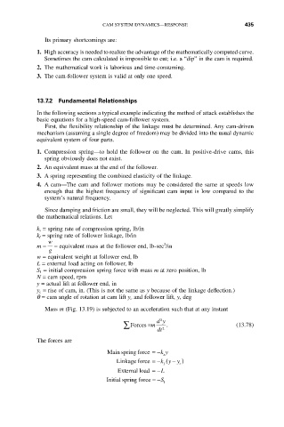
Mass m (Fig. 13.19) is subjected to an acceleration such that at any instant
dy
2
 Forces =m . (13.78)
dt 2
The forces are
Main spring force =-ky
s
Linkage force =- ( - )
ky y
f c
External load =-L
Initial spring force =-S
1