Page 452 - Cam Design Handbook
P. 452
THB13  9/19/03  7:56 PM  Page 440

          440                      CAM DESIGN HANDBOOK

          nomial indicates finite acceleration values y c≤ at the ends (infinite jerk); vibrations result.
          This condition can be alleviated by the use of special ramps. However, if we desire that
          the cam acceleration curve have finite values of jerk, a fourth-order boundary condition
          [for follower y = f(q)] equal to zero at the ends is required. The 5-6-7-8-9 polynomial
          family having the following basic equation fulfills this condition:
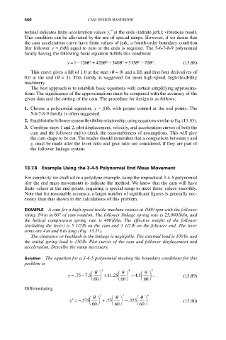
                           y =-126q  5  + 420540q  7  + 315q  8  - 70q .  (13.88)
                                           -
                                        q
                                                           9
                                         6
                             1
             This curve gives a lift of 1.0 at the start (q = 0) and a lift and first four derivatives of
          0.0  at  the  end  (q = 1).  This  family  is  suggested  for  most  high-speed,  high-flexibility
          machinery.
             The best approach is to establish basic equations with certain simplifying approxima-
          tions. The significance of the approximations must be compared with the accuracy of the
          given data and the cutting of the cam. The procedure for design is as follows:
          1. Choose a polynomial equation, y = f(q), with proper control at the end points. The
             5-6-7-8-9 family is often suggested.
          2. Establish the follower system flexibility relationship, using equations similar to Eq. (13. 83).
          3. Combine steps 1 and 2, plot displacement, velocity, and acceleration curves of both the
             cam and the follower end to check the reasonableness of assumptions. This will give
             the cam shape to be cut. The reader should remember that a comparison between y and
             y c must be made after the lever ratio and gear ratio are considered, if they are part of
             the follower linkage system.


          13.7.8 Example Using the 3-4-5 Polynomial End Mass Movement
          For simplicity we shall solve a polydyne example, using the impractical 3-4-5 polynomial
          (for the end mass movement) to indicate the method. We know that the cam will have
          finite values at the end points, requiring a special ramp to meet these values smoothly.
          Note that for reasonable accuracy, a larger number of significant figures is generally nec-
          essary than that shown in the calculations of this problem.

          EXAMPLE A cam for a high-speed textile machine rotates at 1000 rpm with the follower
          rising 3/4in in 60° of cam rotation. The follower linkage spring rate is 25,000lb/in, and
          the  helical  compression  spring  rate  is  400lb/in.  The  effective  weight  of  the  follower
          (including the lever) is 5 1/2lb on the cam and 3 1/2lb on the follower end. The lever
          arms are 4in and 6in long (Fig. 13.21).
             The clearance or backlash in the linkage is negligible. The external load is 100lb, and
          the initial spring load is 150lb. Plot curves of the cam and follower displacement and
          acceleration. Describe the ramp necessary.

          Solution  The equation for a 3-4-5 polynomial meeting the boundary conditions for this
          problem is
                                    Ê q  ˆ  3  Ê q  ˆ  4  Ê q  ˆ  5
                           y = .75  - .7 5  +11 .25  - .45  .          (13.89)
                                    Ë  60 ¯   Ë 60 ¯   Ë  60 ¯
          Differentiating
                                   Ê q  ˆ  2  Ê q  ˆ  3  Ê q  ˆ  4
                            y ¢ =-.375  + .75    -.375                 (13.90)
                                   Ë  60 ¯  Ë  60 ¯  Ë  60 ¯

