
Page 457 - Cam Design Handbook
P. 457
THB13 9/19/03 7:56 PM Page 445
CAM SYSTEM DYNAMICS—RESPONSE 445
1.0
8
y
0.8 y ≤ 6
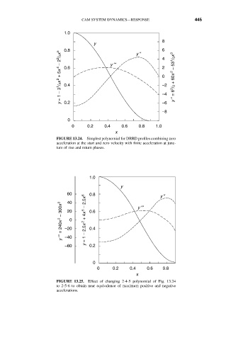
y = 1 – 3 1 / 3x 2 + 5x 4 – 2 2 / 3x 5 0.6 y ¢≤ 2 y ≤ = 6 2 / 3 + 60x 2 – 53 1 / 3x 3
4
0
0.4
–2
–4
0.2
–6
–8
0
0 0.2 0.4 0.6 0.8 1.0
x
FIGURE 13.24. Simplest polynomial for DRRD profiles combining zero
acceleration at the start and zero velocity with finite acceleration at junc-
ture of rise and return phases.
1.0
y
60 0.8 y ≤
40
y ¢≤ = 240x 2 – 300x 3 –20 0 y = 1 – 2.5x 2 + 4x 5 – 2.5x 6 0.6 y ¢≤
20
0.4
–40
–60 0.2
0
0 0.2 0.4 0.6 0.8
x
FIGURE 13.25. Effect of changing 2-4-5 polynomial of Fig. 13.24
to 2-5-6 to obtain near equivalence of maximum positive and negative
accelerations.