
Page 458 - Cam Design Handbook
P. 458
THB13 9/19/03 7:56 PM Page 446
446 CAM DESIGN HANDBOOK
0.360 0.0024
0.320 0.0020
0.280 0.0016
0.240 2-8-10-12-18 0.0012
2-24-26-28-50
y (inches) 0.200 2-8-10-12-18 0.0008 y ≤ (inches per time unit 2 )
2-24-26-28-50
2-16-18-20-34
0.0004
0.160
0.120 2-12-14-16-26 2-20-22-24-42 0
–0.0004
0.080
0.040 –0.0008
0 0.1 0.2 0.3 0.4 0.5 0.6 0.7 0.8 0.9 1.0
x
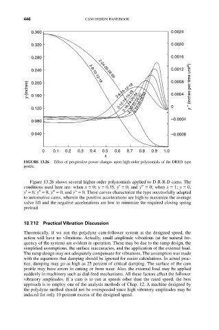
FIGURE 13.26. Effect of progressive power changes upon high-order polynomials of the DRRD type
profile.
Figure 13.26 shows several higher-order polynomials applied to D-R-R-D cams. The
conditions used here are: when x = 0; y = 0.35, y¢= 0, and y = 0; when x = 1; y = 0,
iv
y¢= 0, y≤= 0, y = 0, and y = 0. These curves characterize the type successfully adapted
to automotive cams, wherein the positive accelerations are high to maximize the average
valve lift and the negative accelerations are low to minimize the required closing spring
preload.
13.7.12 Practical Vibration Discussion
Theoretically, if we run the polydyne cam-follower system at the designed speed, the
action will have no vibrations. Actually, small amplitude vibrations (at the natural fre-
quency of the system) are evident in operation. These may be due to the ramp design, the
simplified assumptions, the surface inaccuracies, and the application of the external load.
The ramp design may not adequately compensate for vibrations. The assumption was made
with the equations that damping should be ignored for easier calculations. In actual prac-
tice, damping may go as high as 25 percent of critical damping. The surface of the cam
profile may have errors in cutting or from wear. Also, the external load may be applied
suddenly in machinery such as dial-feed mechanisms. All these factors affect the follower
vibratory amplitudes. If a cam is to run at speeds other than the rated speed, the best
approach is to employ one of the analysis methods of Chap. 12. A machine designed by
the polydyne method should not be overspeeded since high vibratory amplitudes may be
induced for only 10 percent excess of the designed speed.