
Page 68 - Cam Design Handbook
P. 68
THB3 8/15/03 12:58 PM Page 56
56 CAM DESIGN HANDBOOK
3.1 INTRODUCTION
In Chap. 2, the characteristics of displacement, velocity, acceleration, and jerk of basic
symmetrical curves were presented. These curves were employed because of their sim-
plicity of mathematical analysis and ease of construction. However, for many machine
performance requirements, as when the cam requires either special functional motions or
must operate at high speeds, the basic symmetrical curves are inadequate and modifica-
tions in curve selection are necessary. These modifications can consist of blending,
skewing, or combining sectors of the cubic curves, simple harmonic curves, cycloidal
curves, constant velocity curves, and constant acceleration curves.
Last, it should be mentioned that cam curve development (not shown) can be accom-
if
if
plished by starting with the fourth derivative (d y/dy ) curve with numerical trial and error
combined with past experience to find the ultimate desired cam shape. Computers are
employed to perform the increment integration in determining the displacement velocity,
acceleration, and jerk curves.
Curve development and selection is one of the primary steps in the design of any cam-
follower system. Later chapters include investigation of the pressure angle, cam curva-
ture, cam torques, lubrication, materials, and necessary fabrication tolerances, among other
things. A typical design evolutionary process will proceed as a series of trade-offs to
produce the final design.
This chapter has two parts:
• complete mathematical development for popular DRD curves
• a simplified procedure for combining sectors of various basic curves
The dwell-rise-dwell (DRD) and dwell-rise-return-dwell (DRRD) curves will be ana-
lyzed. The rise-return-rise (RRR) curve is not presented since the eccentric mechanism of
Chap. 15 satisfies the action in a simple, reliable, less expensive way. The RRR curve is
also best for high-speed requirements because it provides a motion curve having continu-
ity in all of its derivatives.
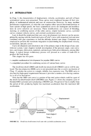
Note that the DRD cam curve is a portion of the total action which could be a part of
the dwell-rise-dwell-return-dwell (DRDRD) cam. Figure 3.1 shows the complete cycle of
blended DRD cycloidal curve producing a DRDRD cam. The period of rise is smaller than
the period of fall, producing higher rise maximum acceleration than the maximum fall
acceleration.
Displacement acceleration Dwell Displacement
+
Dwell
+
Cycloidol –
Dwell – acceleration b 2p
Cam Angle q
Time, t
FIGURE 3.1. Dwell-rise-dwell-return-dwell cam with cycloidal acceleration curves.