
Page 73 - Cam Design Handbook
P. 73
THB3 8/15/03 12:58 PM Page 61
MODIFIED CAM CURVES 61
Acceleration, y" or y ¨ Dwell
Dwell
b b b b
b
8 4 8 2
Cam angle q
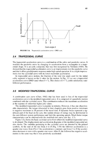
FIGURE 3.4. Trapezoidal acceleration curve—DRD cam.
3.4 TRAPEZOIDAL CURVE
The trapezoidal acceleration curve is a combination of the cubic and parabolic curves. It
modifies the parabolic curve by changing its acceleration from a rectangular to a trape-
zoidal shape. It is an early composite that was first recognized by Neklutin (1969). He
showed that the trapezoidal acceleration curve is an improvement over the parabolic curve
and that it offers good dynamic response under high-speed operation. It is a slight improve-
ment over the cycloidal curve with its lower maximum acceleration.
In trapezoidal curve motion, the fraction of the total rise angle used for the initial
cubic segment is known as the b value for the motion. In Fig. 3.4 we see a trapezoidal
1
1
acceleration curve (DRD cam) where b = / 8 . This choice of b = / 8 yields satisfactory cam-
follower performance.
3.5 MODIFIED TRAPEZOIDAL CURVE
A combination cam curve (Chen, 1982) that has been used in lieu of the trapezoidal
acceleration curve is the modified trapezoidal curve. It is composed of a parabolic motion
combined with the cycloidal curve. This combination reduces the maximum acceleration
at the expense of somewhat higher jerk values.
The modified trapezoidal curve is popular in industry. However, it has one objection-
able characteristic: the torque (discussed in later chapters) goes from positive maximum
to negative maximum in 20 percent of the travel time. If dynamic forces represent a sig-
nificant part of the load on the cam, this sudden release of energy may be detrimental to
the cam-follower system performance and limit the operating speeds. Much better torque
characteristics can be obtained with the modified sine curve (see Sec. 3.7).
Figure 3.5a shows the basic cycloidal curve from which the modified trapezoidal curve
is developed. The displacement and acceleration diagrams of the modified trapezoidal are
also shown. The variables pertaining to the cycloidal curve are denoted by the primed
symbols. At the start of the rise from A to B (Fig. 3.5b) the follower acceleration is a
quarter sine wave; from B to C the acceleration is constant; and from C to D the acceler-
ation decreases to zero with a quarter sine wave. After D, the follower has negative accel-
eration in the same way that it was positively accelerated.