
Page 104 - Carbon Nanotubes
P. 104
et
94 A. FONSECA al.
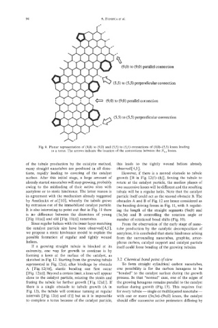
(9,O) to (9,O) parallel connection
(53) to (53) perpendicular connection
(9,O) parallel connection
(53) to (55) perpendicular connection
Fig. 9. Planar representation of (9,O) to (9,O) and (5,5) to (53) connections of (9,O)-(5,5) knees leading
to a torus. The arrows indicate the location of the connections between the Nn,c knees.
of the tubule production by the catalytic method, this leads to the tightly wound helices already
many straight nanotubes are produced in all direc- observed [4,5].
tions, rapidly leading to covering of the catalyst However, if there is a second obstacle to tubule
surface. After this initial stage, a large amount of growth [B in Fig. 12(f)-(h)], forcing the tubule to
already started nanotubes will stop growing, probably rotate at the catalyst particle, the median planes of
owing to the misfeeding of their active sites with two successive knees will be different and the resulting
acetylene or to steric hindrance. The latter reason is tubule will be a regular helix. Note that the catalyst
in agreement with the mechanism already suggested particle itself could act as the second obstacle B. The
by Amelinckx et aL[10], whereby the tubule grows obstacles A and B of Fig. 12 axe hence considered as
by extrusion out of the immobilized catalyst particle. the bending driving forces in Fig. 11, with A regulat-
It is also interesting to point out that in Fig. 11 there ing the length of the straight segments (9n,0) and
is no difference between the diameters of young (5n,5n) and B controlling the rotation angle or
[Fig. ll(a)] and old [Fig. ll(c)] nanotubes. number of rotational bond shifts (Fig. 10).
Since regular helices with the inner layer matching From the observation of the early stage of nano-
the catalyst particle size have been observed[4,5], tube production by the catalytic decomposition of
we propose a steric hindrance model to explain the acetylene, it is concluded that steric hindrance arising
possible formation of regular and tightly wound from the surrounding nanotubes, graphite, amor-
helices. phous carbon, catalyst support and catalyst particle
If a growing straight tubule is blocked at its itself could force bending of the growing tubules.
extremity, one way for growth to continue is by
forming a knee at the surface of the catalyst, as
sketched in Fig. 12. Starting from the growing tubule 3.2 Chemical bond point of view
represented in Fig. 12(a), after blockage by obstacle To form straight cylindrical carbon nanotubes,
A [Fig. 12(b)], elastic bending can first occur one possibility is for the carbon hexagons to be
[Fig. 12(c)]. Beyond a certain limit, a knee will appear “bonded” to the catalyst surface during the growth
close to the catalyst particle, relaxing the strain and process. In that “normal” case, one of the edges of
freeing the tubule for further growth [Fig. 12(d)]. If the growing hexagons remains parallel to the catalyst
there is a single obstacle to tubule growth (A in surface during growth (Fig. 13). This requires that
Fig. 12), the tubule will continue turning at regular for every tubule - single or multilayered nanotube -
intervals [Fig. 12(e) and (f)] but as it is impossible with one or more (5n,5n)-(9n,O) knees, the catalyst
to complete a torus because of the catalyst particle, should offer successive active perimeters differing by