
Page 105 - Carbon Nanotubes
P. 105
Graphitizable coiled carbon nanotubes 95
a)
.-
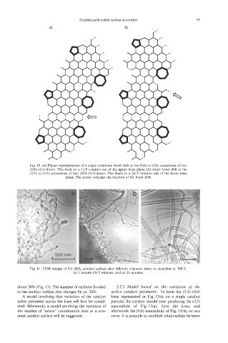
Fig. 10. (a) Planar representation of a single rotational bond shift at the (9,O) to (9,O) connection of two
(9,0t(5,5) knees. This leads to a 2n/9 rotation out of the upper knee plane; (b) single bond shift at the
(5,5) to (5,s) connection of two (9,O)-(5,5) knees. This leads to a 2n/5 rotation out of the lower knee
plane. The arrow indicates the location of the bond shift.
Fig. 11. TEM images of Co-SO, catalyst surface after different exposure times to acetylene at 700°C:
(a) 1 minute; (b) 5 minutes; and (c) 20 minutes.
about 20% (Fig. 13). The number of carbons bonded 3.2.1 Model based on the variation of the
to the catalyst surface also changes by ca. 20%. active catalyst perimeter. To form the ($5)-(9,O)
A model involving that variation of the catalyst knee represented in Fig. 13(c) on a single catalyst
active perimeter across the knee will first be consid- particle, the catalyst should start producing the (53)
ered. Afterwards, a model involving the variation of nanotubule of Fig. 13(a), form the knee, and
the number of “active” coordination sites at a con- afterwards the (9,O) nanotubule of Fig. 13(b), or oice
stant catalyst surface will be suggested. versa. It is possible to establish relationships between