
Page 107 - Carbon Nanotubes
P. 107
Graphitizable coiled carbon nanotubes 97
According to Amelinckx et al.[9], this switch could
be a consequence of the rotation of an ovoid
catalyst particle. However, from this model, during
the production of the parallel hexagons, a complete
“catalyst-tubule bonds rearrangement” must occur
after each hexagonal layer is produced. Otherwise,
as seen from the translation of the catalyst particle
in a direction perpendicular to its median plane,
the catalyst would get completely out of the
growing tubule. Since a mechanism involving this
“catalyst-tubule bonds rearrangement” is not very
likely, we shall now try to explain the growth of
a coiled tubule using a model based on the
variation of the number of active coordination
sites at a constant catalyst surface by a model
which does not involve “catalyst-tubule bonds
rearrangement”.
3.2.2 Model based on the variation of the
number of “active” coordination sites at the cata-
lyst surface. The growth of tubules during the
decomposition of acetylene can be explained in three
steps, which are the decomposition of acetylene, the
initiation reaction and the propagation reaction. This
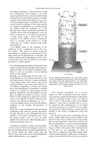
is illustrated in Fig. 14 by the model of a (5,5) tubule
growing on a catalyst particle:
--.
- First, dehydrogenative bonding of acetylene to the
catalyst surface will free hydrogen and produce C2
moieties bonded to the catalyst coordination sites.
These C, units are assumed to be the building
blocks for the tubules. C,H2 flow
- Secondly, at an initial stage, the first layer of C,
units diffusing out of the catalyst remains at a Van Fig. 14. Schematic representation of a (5,s) tubule growing
der Waals distance from the C2 layer coordinated on the corresponding catalyst particle. The decomposition
of acetylene on the same catalyst particle is also represented.
to the catalyst surface. Then, if the C, units of that The catalyst contains many active sites but only those
outer layer bind to one another, this will lead to a symbolized by grey circles are directly involved in the (5,s)
half fullerene. Depending on whether the central tubule growth.
axis of that half fullerene is a threefold or a fivefold
rotation axis, a (9n,0) or a (5n,5n) tubule will start
growing, respectively. The half fullerene can also 3.2.2.1 Growth mechanism of a (5n,5n)
grow to completion instead of starting a nanotu- tubule, over 20n coordination sites of the catalyst.
bule[17]. This assumption is reinforced by the fact The growth of a general (5n,5n) tubule on the catalyst
that we have detected, by HPLC and mass spec- surface is illustrated by that of the (5,5) tubule in
trometry, the presence of fullerenes C,,, C,,, ... Figs 14 and 15. The external circles of the Schlegel
CIg6 in the toluene extract of the crude nanotubules diagrams in Fig. 15(a)-(c) represent half c60 cut at
produced by the catalytic decomposition of the equatorial plane perpendicular to its fivefold
acetylene. rotational symmetry axis or the end of a (5,5) tubule.
- Third, the C2 units are inserted between the catalyst The equatorial carbons bearing a vacant bond are
coordination sites and the growing nanotubule bonded to the catalyst coordinatively [Fig. 15(a)
(Fig. 14). The last C2 unit introduced will still be and (a’)].
bonded to the catalyst coordination sites. From For the sake of clarity, ten coordination sites are
the catalyst surface, a new C, unit will again drawn a little further away from the surface of the
displace the previous one, which becomes part of particle in Fig. 15(a)-(c). These sites are real surface
the growing tubule, and so on. sites and the formal link is shown by a solid line. In
this way the different C, units are easily distinguished
We shall now attempt to explain, from the chemi- in the figure and the formation of six-membered
cal bond point of view, the propagation reaction at rings is obvious. The planar tubule representations
the basis of tubule growth. A growth mechanism for of Fig. 15(a‘)-(c’) are equivalent to those in
the (5n,5n) tubule, the (9n,0) tubule and the Fig. 15 (a)-(c), respectively. The former figures allow
(9n,0)-( 5n,5n) knee, which are the three fundamental a better understanding of tubule growth. Arriving C2
tubule building blocks, is also suggested. units are first coordinated to the catalyst coordination