
Page 108 - Carbon Nanotubes
P. 108
et
98 A. FONSECA al.
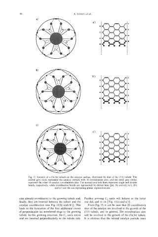
Fig. 15. Growth of a (5n,5n) tubule on the catalyst surface, illustrated by that of the (5,5) tubule. The
central grey circle represents the catalyst particle with 10 coordination sites, and the small grey circles
represent the other 10 catalyst coordination sites. The normal and bold lines represent single and double
bonds, respectively, while coordinative bonds are represented by dotted lines [(a), (b) and (c)]; (a'), (b)
and (c') are the corresponding planar representations.
sites already coordinated to the growing tubule and, Further arriving C2 units will behave as the latter
finally, they are inserted between the tubule and the one did, and so on [Fig. 15(c) and (c')].
catalyst coordination sites Fig. 15(b) and (b)]. This From Fig. 15, it can be seen that 20 coordination
leads to the formation of the first additional crown sites of the catalyst are involved in the growth of the
of perpendicular six membered rings to the growing (5,5) tubule, and in general, 20n coordination sites
tubule. In this growing structure, the C2 units arrive will be involved in the growth of the (5454 tubule.
and are inserted perpendicularly to the tubule axis. It is obvious that the related catalyst particle must