
Page 112 - Carbon Nanotubes
P. 112
Graphitizable coiled carbon nanotubes 101
of the five-membered ring [Fig. 17(d)]. Note also in Fig. 18(f)] leads to positioning of the seven-
that only six new C, units are shown in Fig. 17(c) membered ring. The closure of that ring, during a
with respect to Fig. 17(b). normal (9n,O) tubule growing step [Fig. 19(g) and
Once the pair of sites is disconnected from the (g')], completes the knee and the following steps will
growing tubule [Fig. 17(d)], an orthogonal C2 unit be the growth of the (9n,O) tubule proceeding as
is inserted below the five membered ring [4" in explained in Fig. 16. Figure 18(g') is a Schlegel
Fig. 17(e)]. The latter inserted C2 unit and the remain- diagram of the (5,5)-(9,O) knee, equivalent to Fig.
ing two cis-polyacetylene C2 segments are finally 18(g). In that diagram it is possible to identify the
displaced by the arrival two orthogonal C2 units C, units introduced at the different growing steps
[Y in Fig. 18(f)]. [Fig. lS(a)-(g)] by their numbering.
The carbon atoms linked to the remaining twenty An important conclusion obtained from the model
coordination sites have now finished to rearrange to based on the variation of the number of coordination
a fivefold symmetry [Fig. 17(f)]. Consecutive inser- sites at the catalyst surface is that all double bonds
tion of the five orthogonal C2 units [lo, 3" and 5") can be localized on the (9n,0)-(5n,5n) knee and
displaced from the catalyst by the arrival of five new connected nanotubes. In fact, in that model, only
Orthogonal C, units closes the seven-membered ring single C-C bonds are formed and there is no double
and completes the knee [Fig. 17(g) and (g')]. Further bond formation during the nanotubule growth. All
growth will yield a (5n,5n) tubule. It will proceed of the double bonds are already localized on the C,
as already explained in Fig. 15. Figure 17(g') is a units or on the inserted cis-polyacetylene chains. As
Schlegel diagram explanation of the (9,O)-( 5,5) knee, seen from Figs 17 and 18, there is no double bond
equivalent to Fig. 17(g). In that diagram it is possible on the sides of the five membered ring and there is
to identify the C, units introduced at the different only one double bond on the seven membered ring.
steps [Fig. 17(a)-(g)] by their numbering. It should also be pointed out that localizing the
3.2.2.4 Growth mechanism of a (5n,5n)- double bonds on the (9n,0)-(5n,5n) knee and con-
(9~0) knee, involving from 20n to 24n coordina- nected tubules was a very difficult task before the
tion sites of the catalyst. The explanation given establishment of this model. Once the double bonds
here to pass from a (9n,0) tubule to a (5n,5n) tubule are localized, after replacing the vacant bonds of the
can also be used backwards to pass from a (5n,5n) (9n,0)-( 5n,5n) knee of Fig. 17(g') by hydrogens, it is
tubule to a (9n,O) tubule. The progressive steps are possible to have a three dimensional view of the knee
illustrated in Fig. 18. The starting point of the knee (Fig. 19). The introduction of the parameters of
is again the blockage of tubule growth at the seven- Fig. 19 into a more sophisticated program can also
membered ring [ 1" in Fig. lX(a)J. The later formation be used in order to minimize the energy and simulate
of the five-membered ring is only a consequence of the real knee angle[18,19].
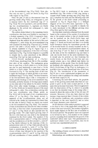
tubule growth blockage at the seven-membered ring. Concerning the multi-shell tubules, the graphitic
Secondly, probably because of the large space created layers of the growing nanotubule described are sup-
on the other side of the tubule by the elastic bending posed to grow on the same catalyst particle, at the
[Fig. 12(b)] after tubule blockage, a cis-butadiene same time as the inner layer does. This is in agreement
[2" in Fig. 18(b)] can be inserted instead of the usual with the observations of Fig. 11, where it is possible
orthogonal 6, units. This cis-butadiene arriving with to see that the diameter range of the young tubes (1
four new coordination sites [black points on minute) is about the same as that of the old ones (20
Fig. 18(b)] will be the head of two cis-polyacetylene minutes). Moreover, it has also been observed that
chains C3" in Fig. 18(c)]. (The freshly arrived C, during a long exposure time (5 hours) of the tubules
segments of the cis-polyacetylene chain, not yet to the reaction conditions, only amorphous carbon
inserted in the tubule, are represented by dotted lines is deposited on the outer layer[4,5], and no tubes
for the sake of clarity.) These two chains are started with larger diameters were observed.
at the five-membered ring [Fig. 18(e)]. The insertion As the diameter of the catalyst particle is supposed
of that cis-butadiene also disturbs the other coordina- to be close to that of the single-shell tubule[20], or
tion sites, so that four other cis-polyacetylene chains to that of the inner tubule[8], the number of graphitic
[4" and 5" in Fig. 18(c)] are also inserted into the layers might depend on the flow rate of acetylene at
growing tubule. The other logical growing steps of the catalyst particle. The graphitic layers are supposed
the (53-(9,O) knee are very close to the mechanism to be formed by the Cz units formed on the catalyst
explained for the (9n,0) tubule. The insertion of the particle, exceeding those needed for the growth of the
first cis-polyacetylene units [3" in Figs 18(c) and (d)] multi-shell tubule inner layer. This generalisation to
and the coordination of the first parallel C2 units [6" multi-layer tubules is just a hypothesis, since we do
in Fig. 18(d)], followed by the insertion of the cis- not have any experimental proof yet.
polyacetylene units [4O in Figs 18(d) and (e)] and the
coordination of parallel C2 units [7" in Fig. 18(e)]
leads to positioning of the five membered ring. The 4. CONCLUSIONS
closure of that ring, followed by the insertion of the The building of knees, tori and helices is described
cis-polyacetylene units [5" and 8" in Figs 18(e) and bv a simple formalism.
(f)] and coordination of three parallel C, units [So Relationships are established between the tubules