
Page 181 - Carbonate Sedimentology and Sequence Stratigraphy
P. 181
172 WOLFGANG SCHLAGER
actual seismic path cross-sectional representation A) surface
A) SP 1 B) SP 1
* v = 1.6 km/s
plotted vertically below SP1, 800
but should really be here
B)
C) SP 1 D) SP 1 1.0
time (s)
coincidendce
addition 1.3
unmigrated postion of reflection
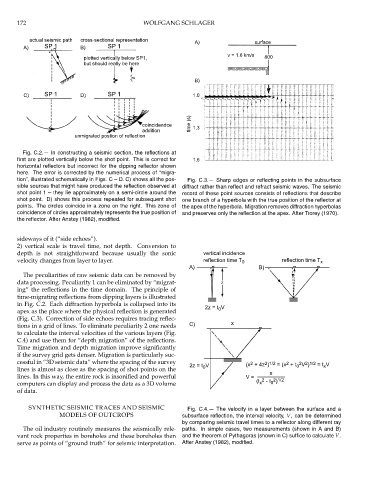
Fig. C.2.— In constructing a seismic section, the reflections at
first are plotted vertically below the shot point. This is correct for 1.6
horizontal reflectors but incorrect for the dipping reflector shown
here. The error is corrected by the numerical process of “migra-
tion”, illustrated schematically in Figs. C – D. C) shows all the pos- Fig. C.3.— Sharp edges or reflecting points in the subsurface
sible sources that might have produced the reflection observed at diffract rather than reflect and refract seismic waves. The seismic
shot point 1 – they lie approximately on a semi-circle around the record of these point sources consists of reflections that describe
shot point. D) shows this process repeated for subsequent shot one branch of a hyperbola with the true position of the reflector at
points. The circles coincide in a zone on the right. This zone of the apex of the hyperbola. Migration removes diffraction hyperbolas
coincidence of circles approximately represents the true position of and preserves only the reflection at the apex. After Trorey (1970).
the reflector. After Anstey (1982), modified.
sideways of it (“side echoes”).
2) vertical scale is travel time, not depth. Conversion to
depth is not straightforward because usually the sonic vertical incidence
velocity changes from layer to layer. reflection time T 0 reflection time T x
A) B)
* * *
The peculiarities of raw seismic data can be removed by
data processing. Peculiarity 1 can be eliminated by “migrat- z
ing” the reflections in the time domain. The principle of
time-migrating reflections from dipping layers is illustrated
in Fig. C.2. Each diffraction hyperbola is collapsed into its 2z = t V
apex as the place where the physical reflection is generated 0
(Fig. C.3). Correction of side echoes requires tracing reflec-
tions in a grid of lines. To eliminate peculiarity 2 one needs C) x
to calculate the interval velocities of the various layers (Fig. *
C.4) and use them for “depth migration” of the reflections.
Time migration and depth migration improve significantly
if the survey grid gets denser. Migration is particularly suc-
cessful in “3D seismic data” where the spacing of the survey 2z = t V (x + 4z ) = (x + t V ) = t V
2
2 2 1/2
2 1/2
2
lines is almost as close as the spacing of shot points on the 0 0 x
x
lines. In this way, the entire rock is insonified and powerful V = 2 2 1/2
x
0
computers can display and process the data as a 3D volume (t - t )
of data.
SYNTHETIC SEISMIC TRACES AND SEISMIC Fig. C.4.— The velocity in a layer between the surface and a
MODELS OF OUTCROPS subsurface reflection, the interval velocity, V, can be determined
by comparing seismic travel times to a reflector along different ray
The oil industry routinely measures the seismically rele- paths. In simple cases, two measurements (shown in A and B)
vant rock properties in boreholes and these boreholes then and the theorem of Pythagoras (shown in C) suffice to calculate V.
serve as points of “ground truth” for seismic interpretation. After Anstey (1982), modified.