
Page 180 - Carbonate Sedimentology and Sequence Stratigraphy
P. 180
APPENDIX C
Principles of reflection seismology
Reflection seismology has become one of the most impor-
tant disciplines for sedimentologists. It is a highly sophis- incident wave reflected wave
ticated technique whose data may be superior to the data
from the best outcrops in certain respects. In addition, the
seismic tool has “seen” much more of the Earth’s sediment
mass than the eyes of field geologists and core loggers to-
gether. Sequence stratigraphy, in particular, relies heavily
on seismic data. There is one catch, however: unlike pho-
tographs, the evidence in seismic data is not immediately 1
obvious. The data result from very delicate measurements
and subsequent processing and some basic understanding 2
of the seismic reflection process is essential for geologists
dealing with seismic data. This is the reason for the brief refracted wave
summary of principles and peculiarities of reflection seis-
mics given below. (See Sheriff and Geldart, 1995, for in-
depth treatment of the subject).
ORIGIN OF SEISMIC REFLECTIONS
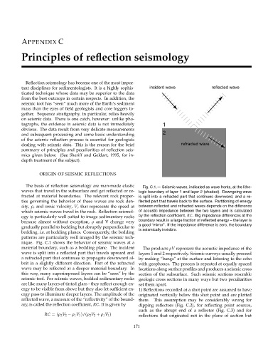
The basis of reflection seismology are man-made elastic Fig. C.1.— Seismic waves, indicated as wave fronts, at the litho-
waves that travel in the subsurface and get reflected or re- logic boundary of layer 1 and layer 2 (shaded). Downgoing wave
fracted at material boundaries. The relevant rock proper- is split into a refracted part that continues downward, and a re-
ties governing the behavior of these waves are rock den- flected part that travels back to the surface. Partitioning of energy
sity, ρ, and sonic velocity, V, that represents the speed at between reflected and refracted waves depends on the difference
which seismic waves travel in the rock. Reflection seismol- of acoustic impedance between the two layers and is calculated
ogy is particularly well suited to image sedimentary rocks by the reflection coefficient, RC. Big impedance differences at the
boundary result in a large fraction of reflected energy – the layer is
because almost without exception, ρ and V change very
a good “mirror”. If the impedance difference is zero, the boundary
gradually parallel to bedding but abruptly perpendicular to
bedding, i.e. at bedding planes. Consequently, the bedding is seismically invisible.
patterns are particularly well imaged by the seismic tech-
nique. Fig. C.1 shows the behavior of seismic waves at a
material boundary, such as a bedding plane. The incident The products ρV represent the acoustic impedance of the
wave is split into a reflected part that travels upward and layers 1 and 2 respectively. Seismic surveys usually proceed
a refracted part that continues to propagate downward al- by making “bangs” at the surface and listening to the echo
beit in a slightly different direction. Part of the refracted with geophones. The process is repeated at equally spaced
wave may be reflected at a deeper material boundary. In locations along surface profiles and produces a seismic cross
this way, many superimposed layers can be “seen” by the section of the subsurface. Such seismic sections resemble
seismic tool. For seismic waves, bedded sedimentary rocks geologic cross sections in many ways but two peculiarities
are like many layers of tinted glass - they reflect enough en- set them apart.
ergy to be visible from above but they also let sufficient en- 1) Reflections recorded at a shot point are assumed to have
ergy pass to illuminate deeper layers. The amplitude of the originated vertically below this shot point and are plotted
reflected wave, a measure of the “reflectivity” of the bound- there. This assumption may be considerably wrong for
ary, is called the reflection coefficient, RC. It is given by dipping reflectors (Fig. C.2), for reflecting point sources,
such as the abrupt end of a reflector (Fig. C.3) and for
RC =(ρ 2 V 2 − ρ 1 V 1 )/(ρ 2 V 2 + ρ 1 V 1 ) reflections that originated not in the plane of section but
171