
Page 138 - Chalcogenide Glasses for Infrared Optics
P. 138
Characterization of Glass Pr operties 115
balance. Sealed in the quartz containers, the finished composition is
guaranteed. Each step of the compounding casting process is con-
trolled by a computer program. A unique program in temperature
and time is developed and stored for each glass composition pro-
duced. Generally, the process, start to finish, takes 48 h.
After the process ends, the quartz container is broken and the
plate is removed. Preliminary evaluation consists of an FTIR scan and
examination for particles, bubbles, and fractures using an infrared
microscope. If the plate is judged good, the anneal cycle is next. The
anneal furnace is large with a good circulation of air. The plate is
heated up to an anneal point near the Tg and then held at this tem-
perature for several hours. Cooldown is slow, perhaps 1° per hour for
the first 20° then faster to room temperature. Anneal cycles vary for
each glass, lasting from 3 to 5 days. The thermal history of the glass
has an effect on the refractive index in the last three to four decimals.
The process should be fixed before the final refractive measurements
are made and the numbers distributed. Once established, the anneal
process should not be changed.
After anneal, the plate is ground flat and parallel and is polished;
transmission is measured and checked against standards and exam-
ined again for particles. Results are recorded on the QC sheet for the
plate. Each plate has a number assigned in the beginning, and the
sheet is kept on file for future reference.
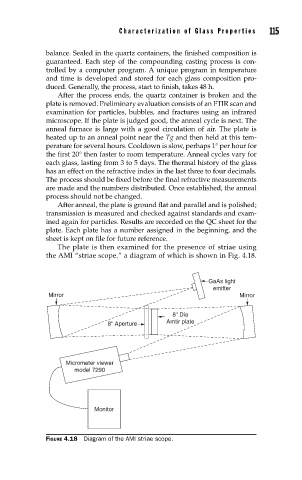
The plate is then examined for the presence of striae using
the AMI “striae scope.” a diagram of which is shown in Fig. 4.18.
GaAs light
emitter
Mirror Mirror
8" Dia
8" Aperture Amtir plate
Micrometer viewer
model 7290
Monitor
FIGURE 4.18 Diagram of the AMI striae scope.